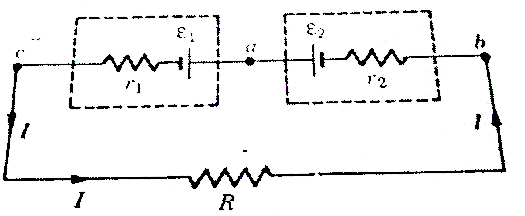
The emf and resistances in the circuit of Fig 27-8a have the following values:
ε1=4.4V.ε2=2.1V,
r1=2.3Ω,r2=1.8Ω,R=5.5Ω
(a) What is the current I in the circuit?
(b) What is the potential difference between the terminals of battery 1 in Fig. 27 8a?
To solve the problem step-by-step, we will first find the current I in the circuit and then determine the potential difference between the terminals of battery 1.
Step 1: Identify the circuit components and values
We have the following values given:
- EMF of battery 1, ϵ1=4.4V
- EMF of battery 2, ϵ2=2.1V
- Internal resistance of battery 1, r1=2.3Ω
- Internal resistance of battery 2, r2=1.8Ω
- External resistance, R=5.5Ω
Step 2: Apply Kirchhoff's Voltage Law (KVL)
According to KVL, the sum of the potential differences in a closed loop must equal zero. We will consider the loop starting from point A and moving clockwise.
The equation can be set up as follows:
ϵ1−I⋅r1−I⋅r2−I⋅R+ϵ2=0
Rearranging gives:
ϵ1−ϵ2=I(R+r1+r2)
Step 3: Substitute the known values
Substituting the known values into the equation:
4.4V−2.1V=I(5.5Ω+2.3Ω+1.8Ω)
Calculating the left side:
2.3V=I(5.5+2.3+1.8)Ω
Calculating the total resistance:
2.3V=I(9.6Ω)
Step 4: Solve for current I
Now, we can solve for I:
I=2.3V9.6Ω≈0.2396A
Rounding gives:
I≈0.24Aor240mA
Step 5: Calculate the potential difference across battery 1
To find the potential difference between the terminals of battery 1, we can use the formula:
VBA=VB−VA=ϵ1−I⋅r1
Substituting the values we have:
VBA=4.4V−(0.24A⋅2.3Ω)
Calculating the drop across r1:
VBA=4.4V−0.552V=3.848V
Rounding gives:
VBA≈3.8V
Final Answers
(a) The current I in the circuit is approximately 0.24A or 240mA.
(b) The potential difference between the terminals of battery 1 is approximately 3.8V.
We have the following values given:
- EMF of battery 1, ϵ1=4.4V
- EMF of battery 2, ϵ2=2.1V
- Internal resistance of battery 1, r1=2.3Ω
- Internal resistance of battery 2, r2=1.8Ω
- External resistance, R=5.5Ω
According to KVL, the sum of the potential differences in a closed loop must equal zero. We will consider the loop starting from point A and moving clockwise.
ϵ1−I⋅r1−I⋅r2−I⋅R+ϵ2=0
Rearranging gives:
ϵ1−ϵ2=I(R+r1+r2)
Substituting the known values into the equation:
4.4V−2.1V=I(5.5Ω+2.3Ω+1.8Ω)
Calculating the left side:
2.3V=I(5.5+2.3+1.8)Ω
Calculating the total resistance:
2.3V=I(9.6Ω)
Now, we can solve for I:
I=2.3V9.6Ω≈0.2396A
Rounding gives:
I≈0.24Aor240mA
To find the potential difference between the terminals of battery 1, we can use the formula:
VBA=VB−VA=ϵ1−I⋅r1
Substituting the values we have:
VBA=4.4V−(0.24A⋅2.3Ω)
Calculating the drop across r1:
VBA=4.4V−0.552V=3.848V
Rounding gives:
VBA≈3.8V
(a) The current I in the circuit is approximately 0.24A or 240mA.
Topper's Solved these Questions
- CIRCUITSBook:RESNICK AND HALLIDAYChapter:CIRCUITSExercise:Checkpoints
Explore 7 Videos
- CIRCUITSBook:RESNICK AND HALLIDAYChapter:CIRCUITSExercise:Problems
Explore 45 Videos
- CENTER OF MASS Book:RESNICK AND HALLIDAYChapter:CENTER OF MASS Exercise:Practice Questions (Integer )
Explore 4 Videos
- CIRCULAR MOTIONBook:RESNICK AND HALLIDAYChapter:CIRCULAR MOTIONExercise:CHECK POINTS
Explore 6 Videos
Similar Questions
Figure 27-12 shows a circuit whose elements have the following values: ε1=3.0V,ε2=6.0V,R1=2.0ΩR2=2.0Ω. The three batteries are ideal batteries. Find the magnitude and direction of the current in each of the three branches
View SolutionFigure 27-11a shows a multiloop circuit containing one ideal battery and four resistances with the following values:
R1=20Ω,R2=20Ω,ε=12V,
R3=30Ω,R4=8.0Ω
(a) What is the current through the battery?
(b) What is the current i2 through R2?
(c) What is the current i3 through R3?
View Solution
Knowledge Check
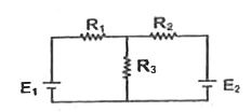
In the circuit shown, E1=7V,E2=7V,R1=R2=1Ω and R3=3Ω respectively. The current through the resistance R3
 Ai=0Bi=2ACV=14VDV=7V
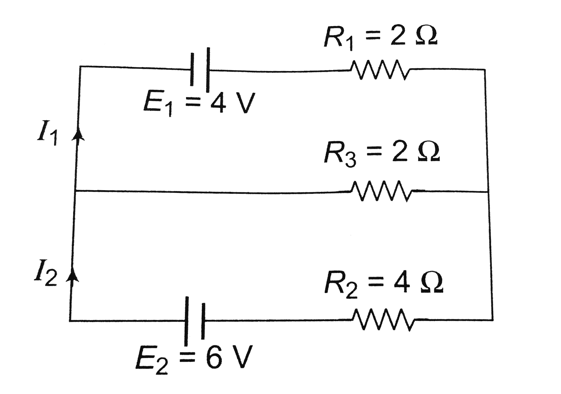
In the circuit shown below E1=4.0V,R1=2Ω,E2=6.0V,R2=4Ω and R3=2Ω. The current I1 is
 A1.6AB1.8AC1.25AD1.0A

In the circuit shown in figure. ε1=3,ε2=2,ε3=6V,R1=2,R4=6Ω,R3=2,R2=4ΩandC=5μF. Find the current in the resistor R3 and the electrical energy stored in the capacitor C.
View SolutionIn Fig. 27-43, the current in resistance 6 is i6=2.80A the resistances are R1=R2=R3=2.00Ω,R4=16.0Ω,R5=8.00ΩandR6=4.00Ω. Wat is the emf of the ideal battery?

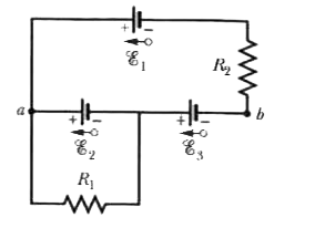
View SolutionIn Fig. 27-63, R1=100Ω,R2=50Ω, and the ideal batteries have emfs, ε1=6.0V,ε2=10V,andε3=4.0V. Find (a) the current in resistor 1, (b) the current in resistor 2, and (c) the potential difference between points a and b.
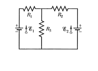
View SolutionIn Fig. 27-37, the ideal batteries have emfs ε1=12.0Vand=ε2=0.500ε1 and the resistances are each 4.00Ω. What is the current in (a) resistance 2 and (b) resistance 3?
View Solution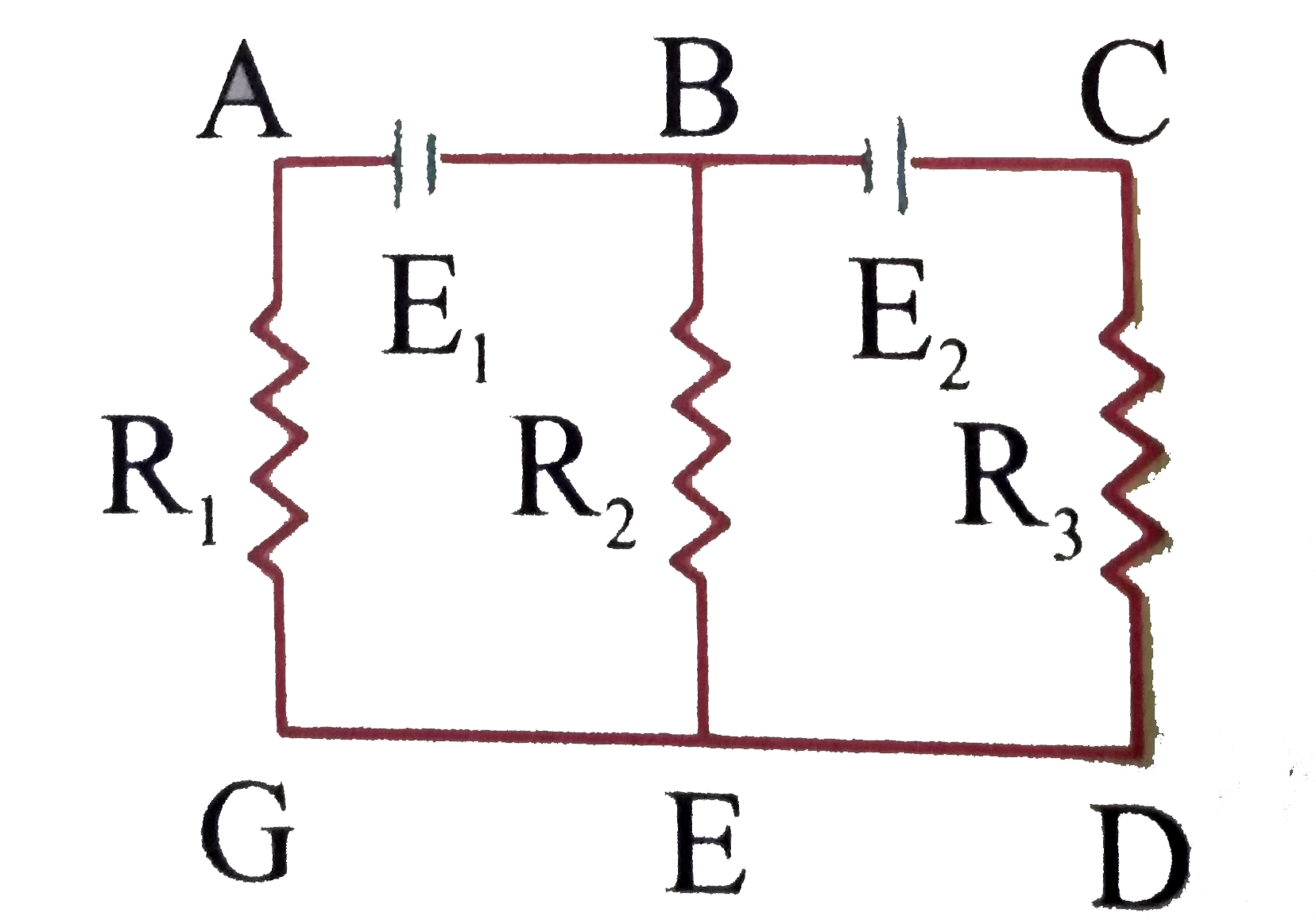
In the given circuit values are as follows
ε=2V,ε2=4V,R1=1Ω and R2=R3=1Ω.
Calculate the current through R1,R2 and R3
View SolutionIn Fig. 4.32 ε1 and ε2 are respectively 2.0 V and 4.0 V the resistances r1,r2 and R are respectively 1.0Ω,2.0Ω and 5.0Ω. Calculate the current in the circuit. Also calculate (i) potential difference between the points b and a, (ii) potential difference between a and c.
View Solution