A thin wire of length L is connected to two adjacent fixed points and carries a current I in the clockwise direction , as shown in the figure. When the system is put in a uniform magnetic field of strength B going into the plane of the paper , the wire takes the shape of a circle . The tension in the wire is
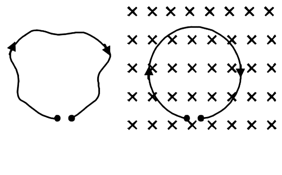
IBL
IBLπ
IBL2π
IBL4π
The correct Answer is:C
Step by step video, text & image solution for A thin wire of length L is connected to two adjacent fixed points and carries a current I in the clockwise direction , as shown in the figure. When the system is put in a uniform magnetic field of strength B going into the plane of the paper , the wire takes the shape of a circle . The tension in the wire is by Physics experts to help you in doubts & scoring excellent marks in Class 12 exams.
Updated on:21/07/2023Similar Questions
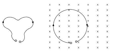
A thin flexible wire of length L is connected to two adjacent fixed points and carries a current I in the clockwise direction, as shown in the figure. When the system is put in a uniform magnetic field of strength B going into the plane of the paper, the wire takes the shape of a circle. The tension in the wire is :
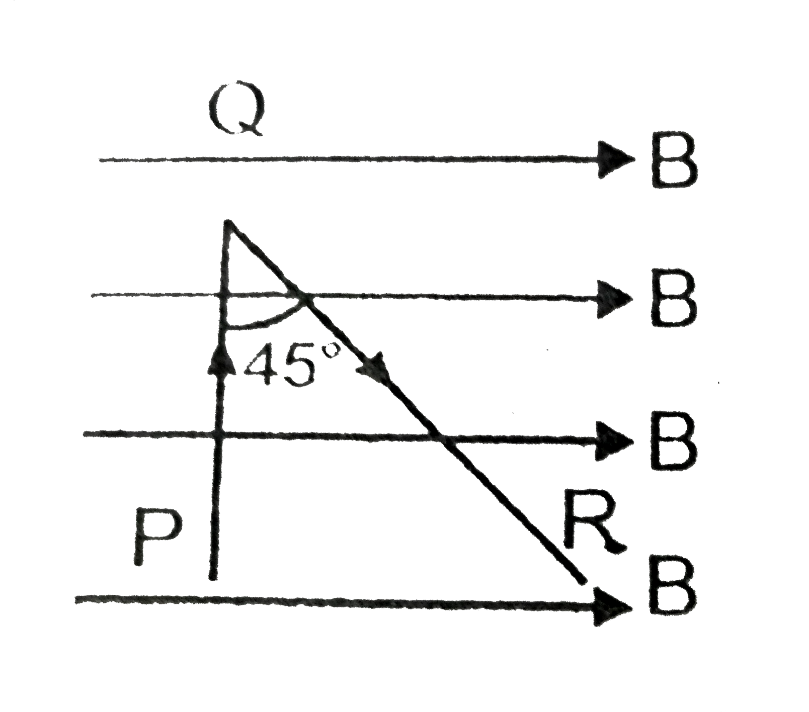
View SolutionA wire PQR carrying a current l is bent as shown in the figure. It is placed in a uniform magnetic field B. What is the ratio of magnitude of the force on PQ to that on QR ?
View Solution
Knowledge Check
A thin flexible wire of length L is connected to two adjacent fixed points and carries a current I in the clockwise direction, as shown in the figure. When the system is put in a uniform magnetic field of strength B going into the plane of the paper, the wire takes the shape of a circle. The tension in the wire is :
 AIBLBIBLπCIBL2πDIBL4π
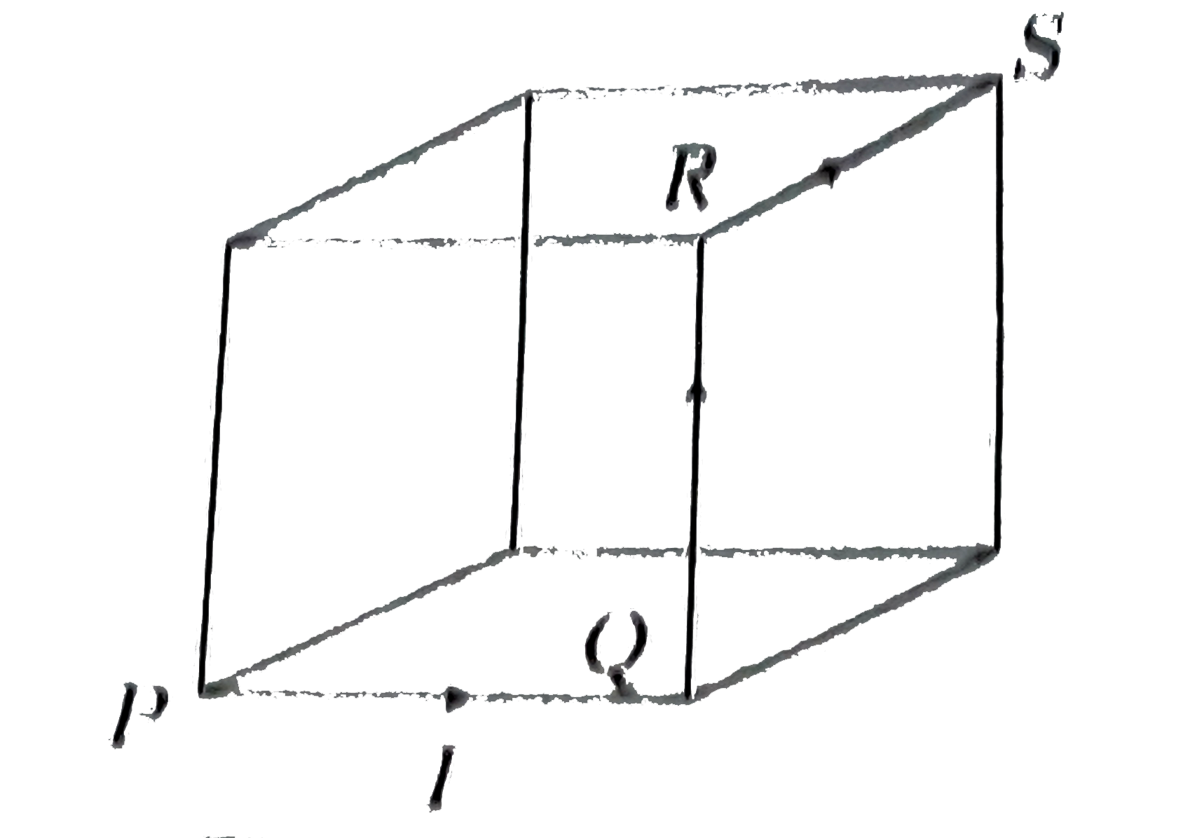
A wires PQRS carrying a current I runs along three edges of a cube of side l as shown in figure. There exists a uniform magnetic field of magnitude B along one of the sides of cube. The magnitude of the force acting on the wire is
 AzeroB√3IBC√2IlBD2Ilb
Two infinitely long wires each carrying current I along the same direction are made into the geometry as shown in the figure. The magnetic field at the point P is
 Aμ0IπrBμ0Ir(1π+14)CZeroDμ0I2πr
the force on current carrying wire placed in uniform magnetic field B as shown in figure is

View SolutionA conducting wire carrying current I is shown in the figure. The magnitude of magnetic field at the point P will be

View SolutionA wire is placed between the poles of two fixed bar magnets as shown in the figure. A small current in the wire is into the plane of the paper. The direction of the magnetic force on the wire is

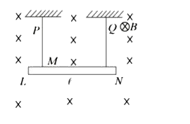
View SolutionA rod of mass M and length l is suspended by two wires P and Q. A uniform magnetic field 'B' is directed into the page. When current through the rod is l. Then the tension in each supporting wire is-
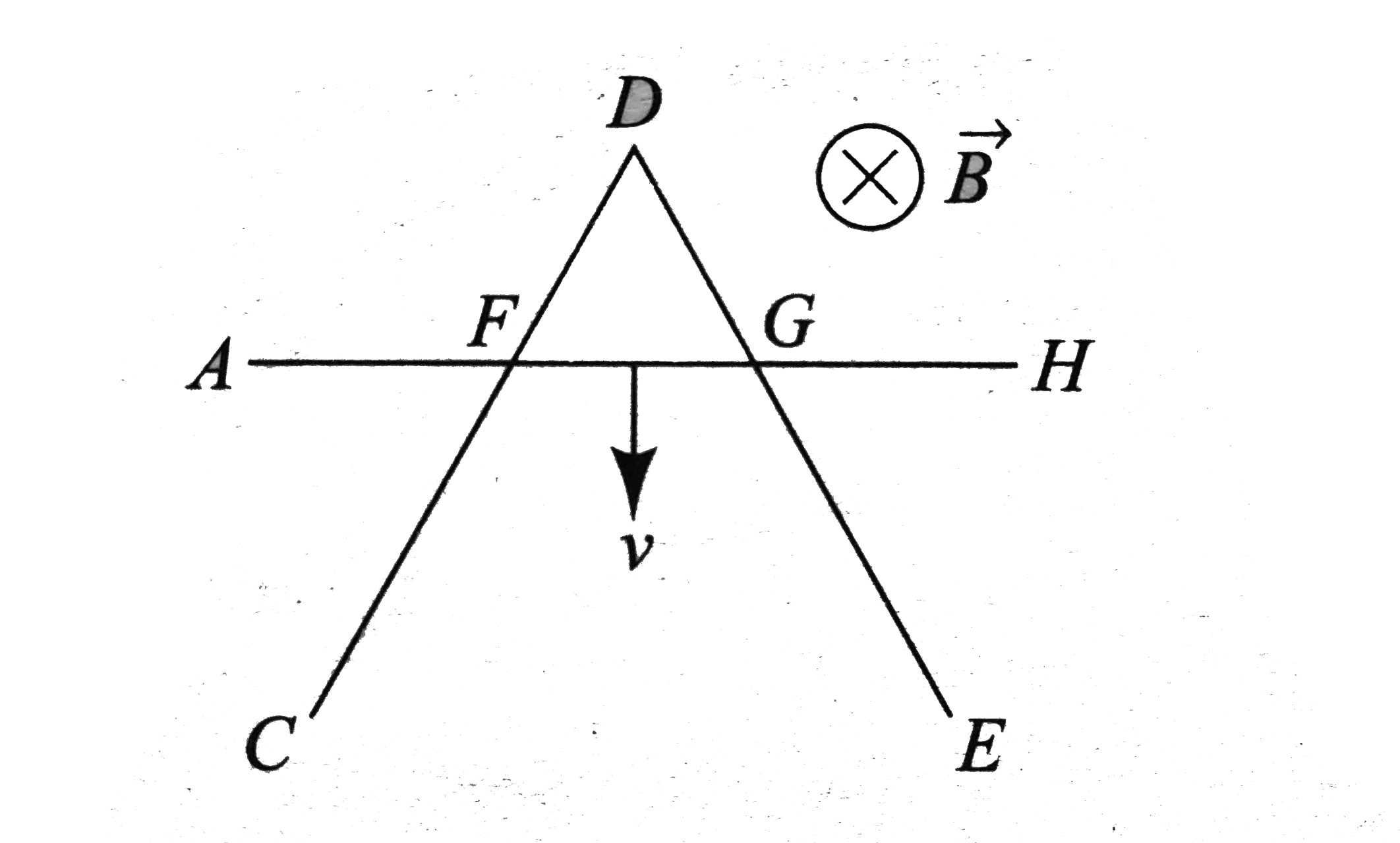
View SolutionA long conducting wire AH is moved over a conducting triangular wire CDE with a constant velocity v in a uniform magnetic field →B directed into the plane of the paper. Resistance per unit length of each wire is ρ. Then
View Solution
