Two inductors (inductors 1 mH, internal resistance 3 ) and (inductance 2mH, internal resistance 4),and a resistor R(resistance) are all connected in parallelacross a 5 V battery. The circuit is switched on at time t=0. The ratio of the maximum to the minimum current drawn from the battery is
The correct Answer is:8
We should know that ideal inductor behaves like an infinite resistance at t = 0 , when circuit is switched on. And it behaves like zero resistance after current is established in the circuit , after a long time. But here inductors are said to have some internal resistance, and hence initially they will behave like an infinite resistance and after a long time they will behave simply like resistance of given value. In one parallel branch, there is one pure resistance .
At t = 0 there would not be any current through the parallel branches containing inductor and current will flow only through branch of pure resistance . it will be the case of minimum current drawn from the battery .
Minimum current drawn from the battery can be written as follows?
A
After a long time, when current sets in branches containing inductors, then resistance of magnitude 3 will be considered to be connected in parallel to each other. Eqivalent resistance of the circuit will be written as follows :
In this case current drawn from the battery will be maximum Hence maximum current drawn from the battery can be written as follows :
A
Ratio of the maximum to minimum current can be written as follows :
Topper's Solved these Questions
- ALTERNATING CURRENT BOOK - MODERN PUBLICATIONCHAPTER - ALTERNATING CURRENT EXERCISE - COMPETITION FILE EXEMPLAR PROBLEMS (OBJECTIVE QUESTIONS ) (Multiple choice question (Type ) )
13 Videos
- ALTERNATING CURRENT BOOK - MODERN PUBLICATIONCHAPTER - ALTERNATING CURRENT EXERCISE - CHAPTER PRACTICE TEST
16 Videos
- ALTERNATING CURRENT BOOK - MODERN PUBLICATIONCHAPTER - ALTERNATING CURRENT EXERCISE - COMPETITION FILE ASSERTION REASON TYPE QUESTIONS
10 Videos
- ATOMS BOOK - MODERN PUBLICATIONCHAPTER - ATOMS EXERCISE - Chapter Practice Test
16 Videos
Similar Questions
Two inductors L1 (inductance 1 mH, internal resistance 3Ω)and L2 (inductance 2 mH, internal resistance 4Ω), and a resistance R (resistance 12Ω)are all connected in parallel across a 5V battery . The circuit is switched on at time t=0. The ratio of the maximum to the minimum current (Imax/Imin) drawn from the battery is :
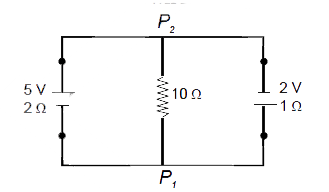
View SolutionA 5 V battery with internal resistance 2Ω and a 2V battery with internal resistance 1Ω are connected to a 10Ω as shown in the figure.

The current in the 10Ω resistance is
View Solution
Knowledge Check
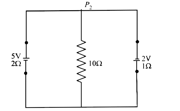
A 5V battery with internal resistance 2Ω and a 2V battery with internal resistance1Ω are connected to a 10Ω resistor as shown in the figure.

The current in the 10Ω resistor isA0.27AP2→P1B0.03AP1→P2C0.03AP2→P1D0.27AP1→P2A 5V battery with internal resistance 2Ω and a 2V battery with internal resistance1Ω are connected to a 10Ω resistor as shown in the figure.

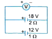
The current in the 10Ω resistor isA0.27 AB0.05 AC0.25 AD0.3 ATwo batteries, one of emf 18 V and internal resistance 2 Ω and the other of emf 12 V and internal resistance 1Ω , are connected in parallel as shown in Fig. The voltmeter V will record a reading of
 A15VB14VC30VD18V
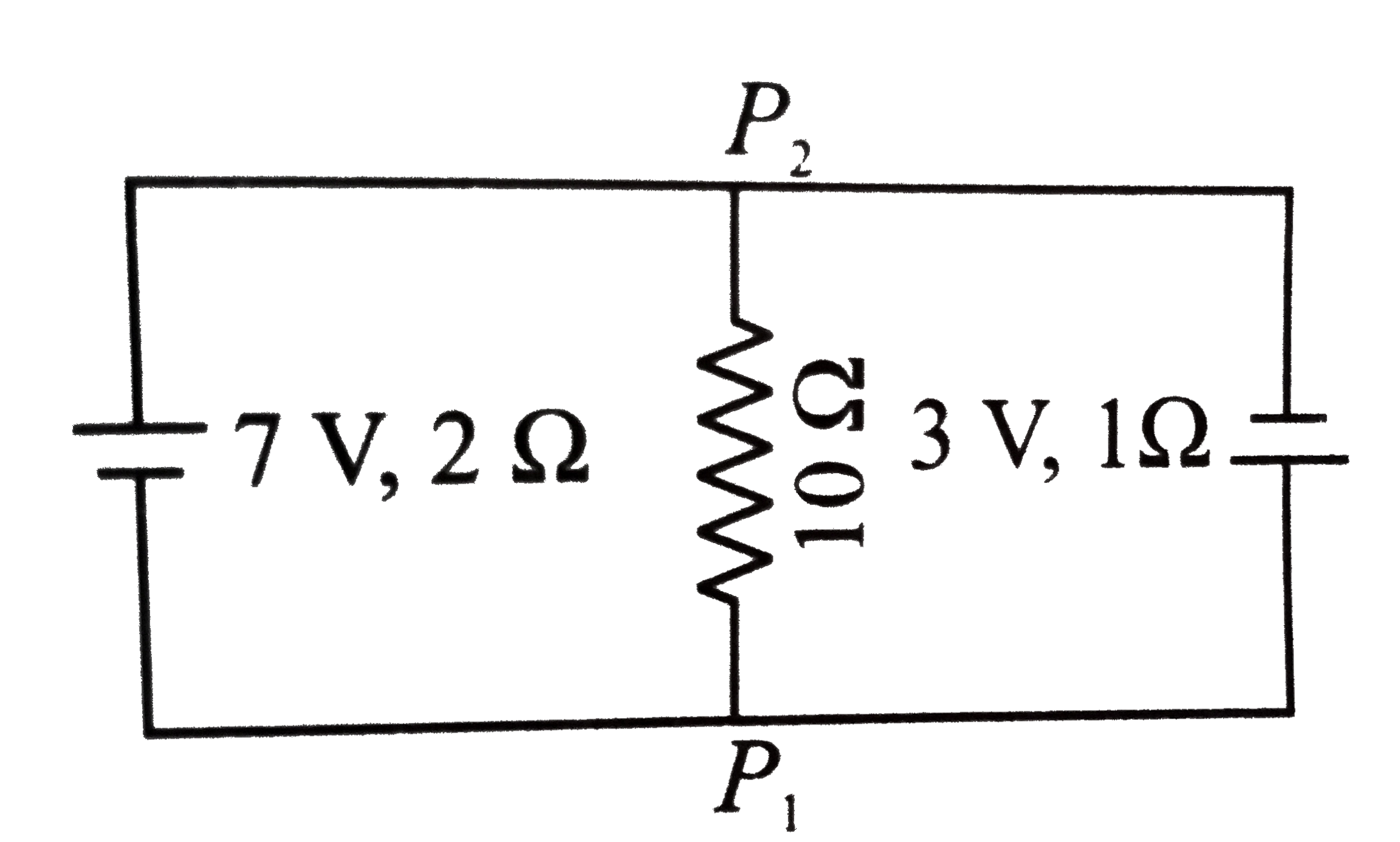
7 V battery with internal resistance 2Ωand3V battery with internal resistance 1Ω are connected to a 10Ω resistors as shown in figure, the current in 10Ω resistor is

View SolutionA coil of inductance 8.4mH and resistance 6 Ω is connected to a 12V battery. The current in the coil is 1.0A at approximately the time.
View SolutionA coil of inductance 8.4 mH and resistance 6(Ω) is connected to a 12 V battery. The current in the coil is 1.0 A at approximately the time
View SolutionTwo resistors of resistances 2Ω and 6Ω are connected in parallel. This combination is then connected to a battery of emf 2 V and internal resistance 0.5Ω. What is the current flowing thrpough the battery ?
View SolutionA coil of inductance 8.4 mH and resistance 6ω is connected to 12 V battery. The current in the coil is 1 A at approximately the time
View Solution
