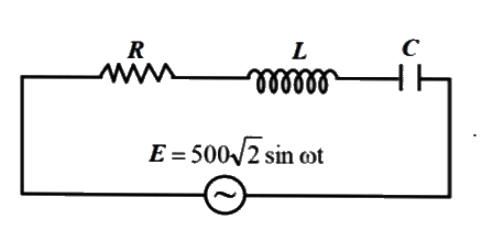
In a series LCR circuit, rms voltage across inductor and capacitor are found ot be 8 V and 5 V respectively. If applied voltage is 5 volts, then what is rms voltage across resistance in volts ?
The correct Answer is:4
To solve the problem step by step, we will use the information provided about the voltages across the inductor (VL), capacitor (VC), and the applied voltage (V).
1. Identify Given Values:
- RMS voltage across the inductor, VL=8V
- RMS voltage across the capacitor, VC=5V
- Applied voltage, V=5V
2. Understand the Phase Relationships:
- In a series LCR circuit, the voltage across the inductor leads the current by 90 degrees, while the voltage across the capacitor lags the current by 90 degrees. Therefore, the voltages across the inductor and capacitor can be treated as vectors in a phasor diagram.
3. Calculate the Net Voltage Across the Inductor and Capacitor:
- The effective voltage across the inductor and capacitor can be calculated as:
VLC=VL−VC
- Substituting the given values:
VLC=8V−5V=3V
4. Apply the Pythagorean Theorem:
- The relationship between the applied voltage, the voltage across the resistance (VR), and the net voltage across the inductor and capacitor can be expressed using the Pythagorean theorem:
V2=V2R+V2LC
- Substituting the known values:
52=V2R+32
- This simplifies to:
25=V2R+9
5. Solve for the Voltage Across the Resistance:
- Rearranging the equation gives:
V2R=25−9=16
- Taking the square root:
VR=√16=4V
Final Answer:
The RMS voltage across the resistance is VR=4V.
---
- RMS voltage across the inductor, VL=8V
- RMS voltage across the capacitor, VC=5V
- Applied voltage, V=5V
- In a series LCR circuit, the voltage across the inductor leads the current by 90 degrees, while the voltage across the capacitor lags the current by 90 degrees. Therefore, the voltages across the inductor and capacitor can be treated as vectors in a phasor diagram.
- The effective voltage across the inductor and capacitor can be calculated as:
VLC=VL−VC
- Substituting the given values:
VLC=8V−5V=3V
- The relationship between the applied voltage, the voltage across the resistance (VR), and the net voltage across the inductor and capacitor can be expressed using the Pythagorean theorem:
V2=V2R+V2LC
- Substituting the known values:
52=V2R+32
- This simplifies to:
25=V2R+9
- Rearranging the equation gives:
V2R=25−9=16
- Taking the square root:
VR=√16=4V
The RMS voltage across the resistance is VR=4V.
Topper's Solved these Questions
- ALTERNATING CURRENT Book:MODERN PUBLICATIONChapter:ALTERNATING CURRENT Exercise:COMPETITION FILE EXEMPLAR PROBLEMS (OBJECTIVE QUESTIONS ) (Multiple choice question (Type ) )
Explore 13 Videos
- ALTERNATING CURRENT Book:MODERN PUBLICATIONChapter:ALTERNATING CURRENT Exercise:CHAPTER PRACTICE TEST
Explore 16 Videos
- ALTERNATING CURRENT Book:MODERN PUBLICATIONChapter:ALTERNATING CURRENT Exercise:COMPETITION FILE ASSERTION REASON TYPE QUESTIONS
Explore 10 Videos
- ATOMS Book:MODERN PUBLICATIONChapter:ATOMS Exercise:Chapter Practice Test
Explore 16 Videos
Similar Questions
In an LCR series circuit the rms voltages across R L and C are found to be 10V,10V and 20Vrespectively.The rms voltage across the entire combination is
View SolutionIn a series LCR circuit, the voltage across an inductor, a capacitor and a resistor are 20 V, 20 V and 40 V, respectively. What is the phase difference between the applied voltage and the current in the circuit ?
View Solution
Knowledge Check
In a series LCR circuit, the voltage across the inductance and capacitance are not
Aout of phase with voltage across resistance by 90∘Bequal in magnitude at resonanceCout of phase with each other by 180∘Din phase with the source voltageIn an LCR series circuit the voltages across R,L and C at resonance are 40Vand60V respectively the applied voltage is .
A60VB40VC160VD√(40)2+(120)2VIn an LCR series circuit the rms voltages across R,L and C are foundd to be 10V,10V and 20V respectively. The rms voltage across the entire combination is
A30VB1VC20VD10√2V
In a series LCR circuit, the voltages across an inductor, a capacitor and a resistor are 30 V, 30 V, 60 V respectively. What is the phase difference between the applied voltage and the current in the circuit ?
View SolutionIn the series L−C−R circuit shown in the figure, the rms voltage across the resistor and inductor are 400 V and 700 V respectively. If the applied voltage is E=500√2sin(ωt), then the peak voltage across the capacitor is

View SolutionIn an LCR series circuit the rms voltages across R L and C are found to be 10V,10V and 20Vrespectively.The rms voltage across the entire combination is
View SolutionIn a series LCR circuit the voltage across an inductor, capacitor and resistor are 20 V, 20 V and 40 V respectively. The phase difference between the applied voltage and the current in the circuit is
View SolutionIn a series LCR circuit the rms voltage across the inductance , capacitance and resistance are respectively 4 V, 8 V and 5 V . The RMS voltage of the AC source in the circuit is
View Solution

