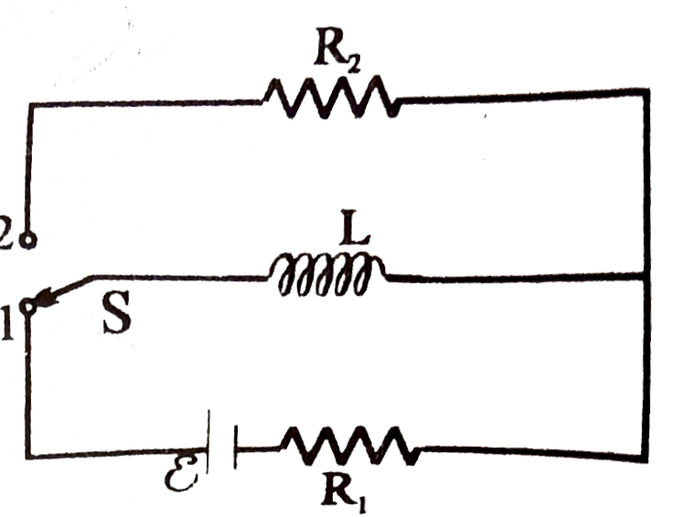
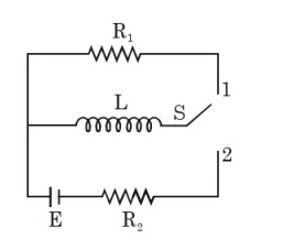
In the circuit shown, the switch S is shifted to position 2 from position 1 at t=0, having been in position 1 for a long time.Find the current in the circuit as a function of time.
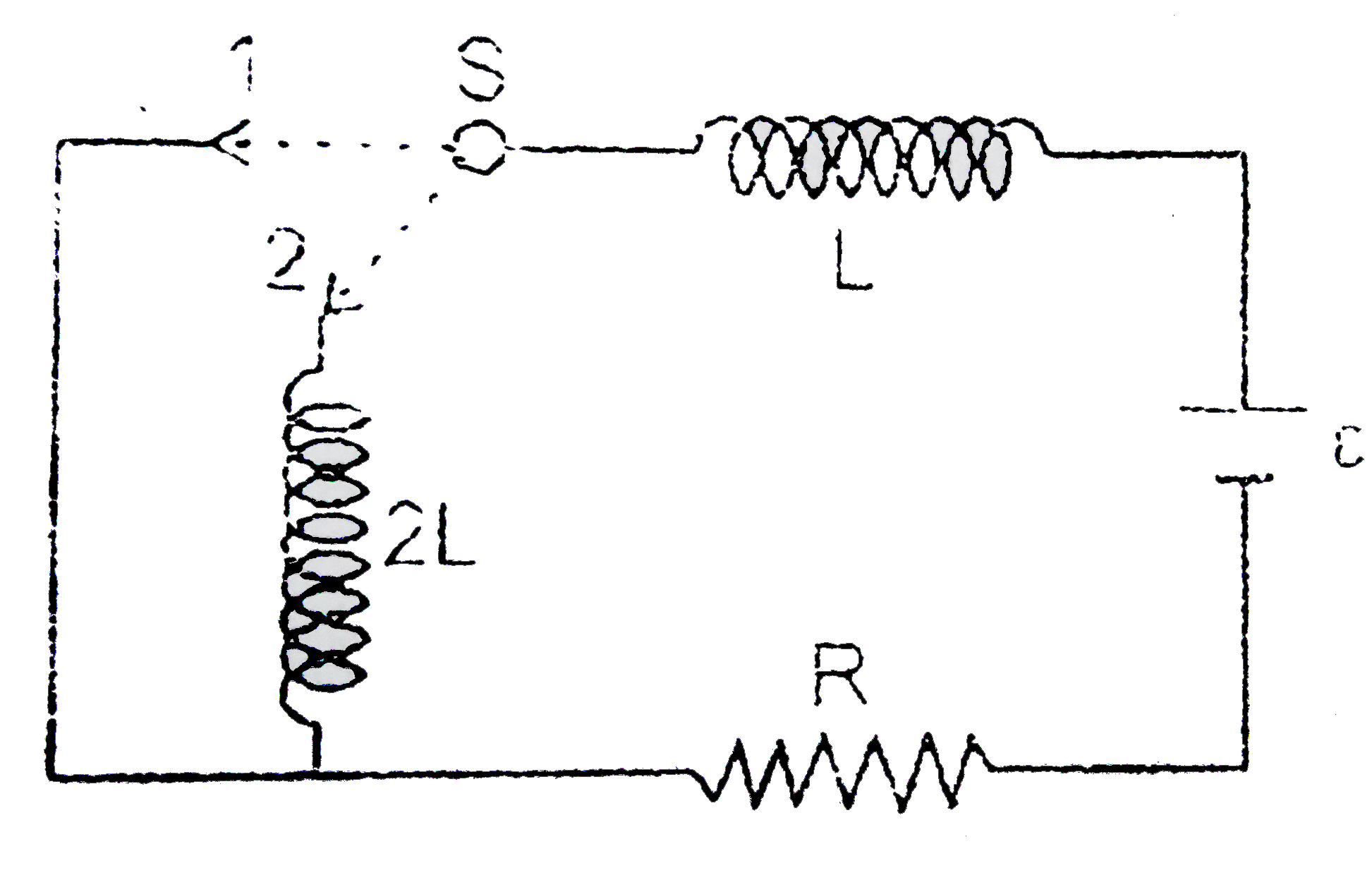
The correct Answer is:I=εR(1−23×e−Rt3L)
Step by step video, text & image solution for In the circuit shown, the switch S is shifted to position 2 from position 1 at t=0, having been in position 1 for a long time.Find the current in the circuit as a function of time. by Physics experts to help you in doubts & scoring excellent marks in Class 12 exams.
Updated on:21/07/2023Similar Questions
Knowledge Check
In the circuit shows in Fig switch S is shifed to position 2 from position 1 at t=0, having been on position 1 for a long time. The current in the circuit just after shifting of switch will be (battery and both the inductors are ideal)
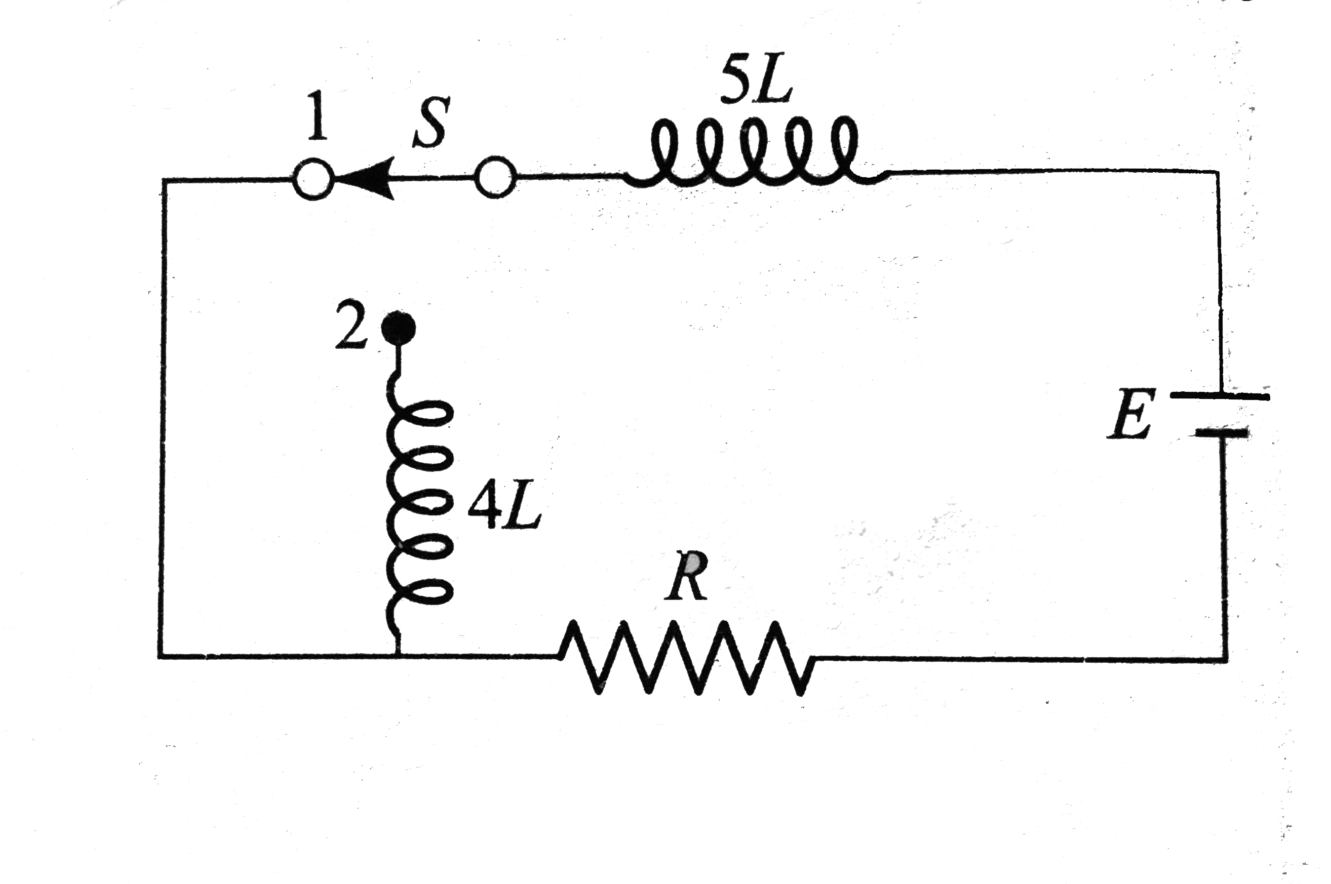 A45ERB54ERC59ERDER
In the given circuit diagram figure, switch Sw is shifted from position 1 to position 2. Then
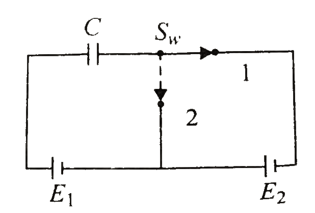 Aa charge of amount CE2 will be supplied to battery E1.Bheat generated in the circuit is CE22/2Ca charge of amount CE2 will be supplied by battery E1.Dheat generated in the circuit is CE1E2/2
In the circuit shown, the switch is shifted from position 1rightarrow 2 at t=0. The switch was initially in position I since a long time. The graph between charge on capacitor C and time 't' is
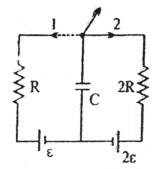 A
A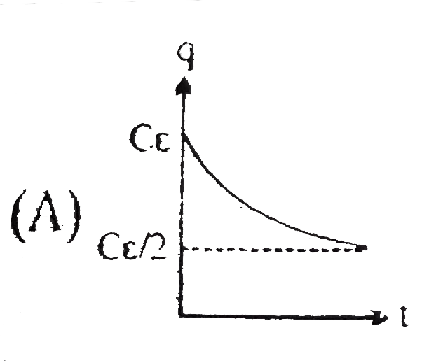 B
B C
C D
D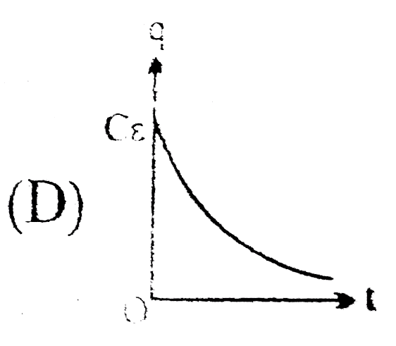
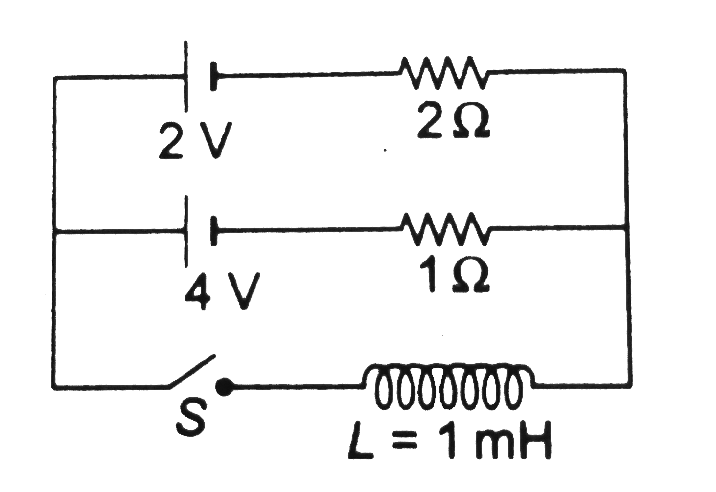
In the circuit shown, switch S is closed at time t=0. Find the current through the inductor as a function of time t.
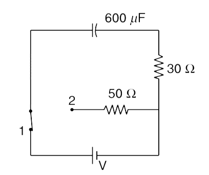
View SolutionIn the circuit shown, after the switch is shifted to position 2 the heat generated in 50Ω resistance is 6J. find the emf (V) of the cell.
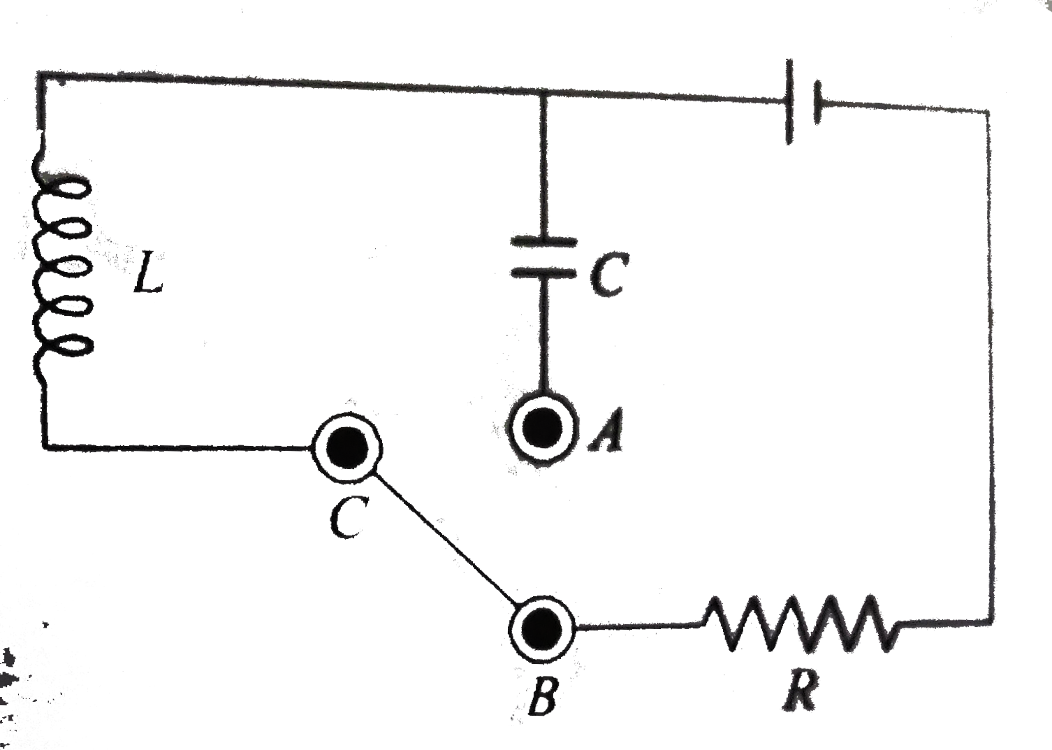
View SolutionIn the circuit shows in Fig the capacitor is initially uncharged and the two - way switch is connected in the position BC. Find the current through the resistence R as a function of time t. After time t=4 ms, the switch is connected in the position AC. Find the frequency of oscillation of the capacitor of the circuit in the position, and the maximum charge on the capacitor C. At what time will the energy stored in the capacitor be one-half of the total energy stored in the circuit? It is given L=2×10⁻⁴H,C=5mF,R=In210Ω and emf of the battery =1V.
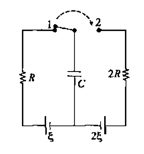
View SolutionIn the circuit shown in figure-3.311, the switch is shifted from position I to 2 at time t = 0. The switch was initially in position I for a long time. The graph between charge on capacitor C and time tis best represented as
View SolutionIn the circuit shown switch S is connected to position 2 for a long time and then joined to position 1. The total heat produced in resistance R1 is:
View Solution

