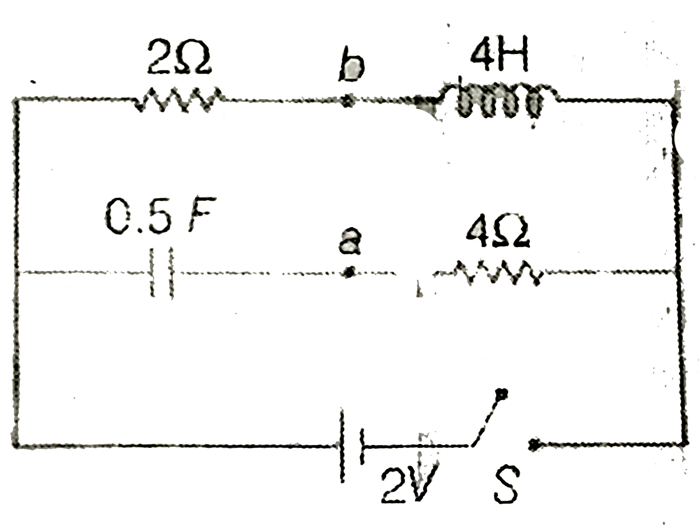
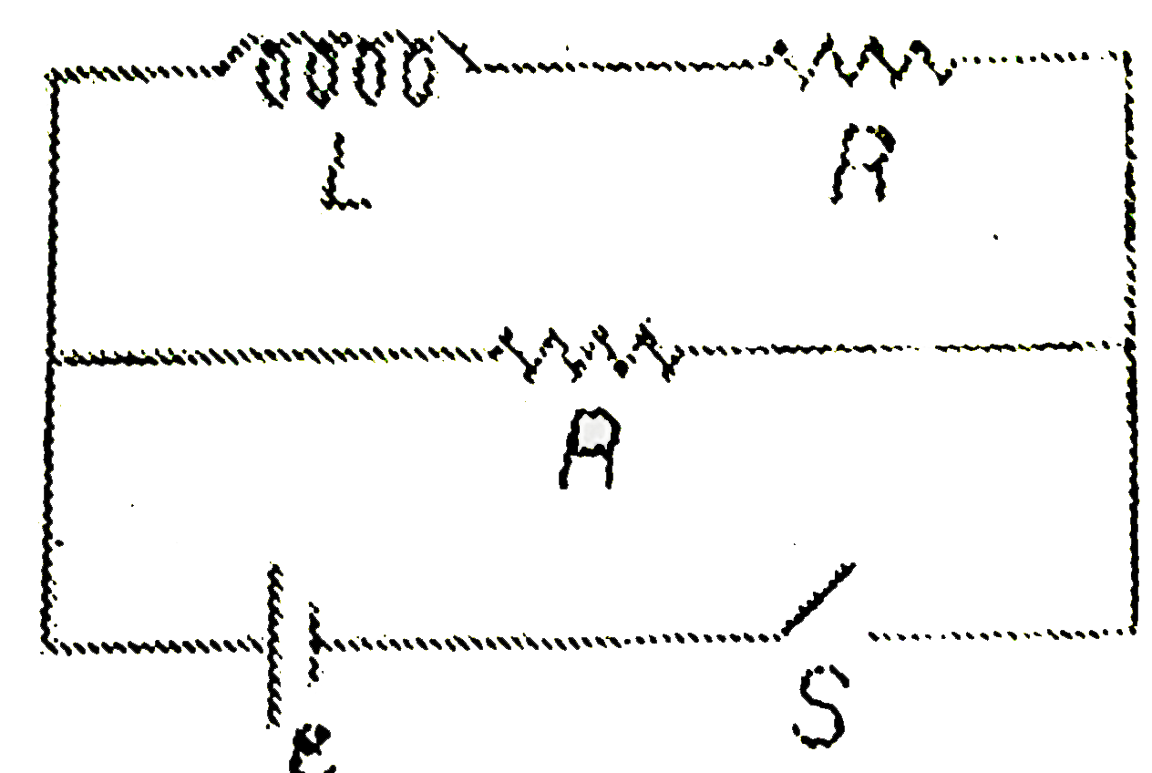
In the circuit diagram shown in the figure the switches S1 and S2 are closed at time t=0.After time t=(0.1)ln2sec, switch S2 is opened.The current in the circuit at time t=0.2n2sec is equal to x32amp.Find out value of x.
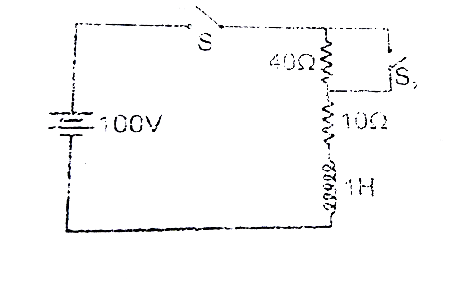
Step by step video, text & image solution for In the circuit diagram shown in the figure the switches S_(1) and S_(2) are closed at time t=0.After time t=(0.1)ln 2sec, switch S_(2) is opened.The current in the circuit at time t=(0.2)/n 2sec is equal to x/32amp.Find out value of x. by Physics experts to help you in doubts & scoring excellent marks in Class 12 exams.
Topper's Solved these Questions
- BOOK - RESONANCECHAPTER - ELECTROMAGNETIC INDUCTIONEXERCISE - Exercis-2 PART 310videos
ELECTROMAGNETIC INDUCTION
- BOOK - RESONANCECHAPTER - ELECTROMAGNETIC INDUCTIONEXERCISE - Exercis-2 PART 46videos
ELECTROMAGNETIC INDUCTION
- BOOK - RESONANCECHAPTER - ELECTROMAGNETIC INDUCTIONEXERCISE - Exercis-2 PART 115videos
ELECTROMAGNETIC INDUCTION
- BOOK - RESONANCECHAPTER - ELECTRODYNAMICSEXERCISE - Advanced level problems31videos
ELECTRODYNAMICS
- BOOK - RESONANCECHAPTER - ELECTROSTATICSEXERCISE - HLP39videos
ELECTROSTATICS
Similar Questions
In the circuit diagram shown in the figure the switches S1 and S2 are closed at time t=0.After time t=(0.1)ln2sec, switch S2 is opened.The current in the circuit at time t=0.2n2sec is equal to x32amp.Find out value of x.
 View Solution
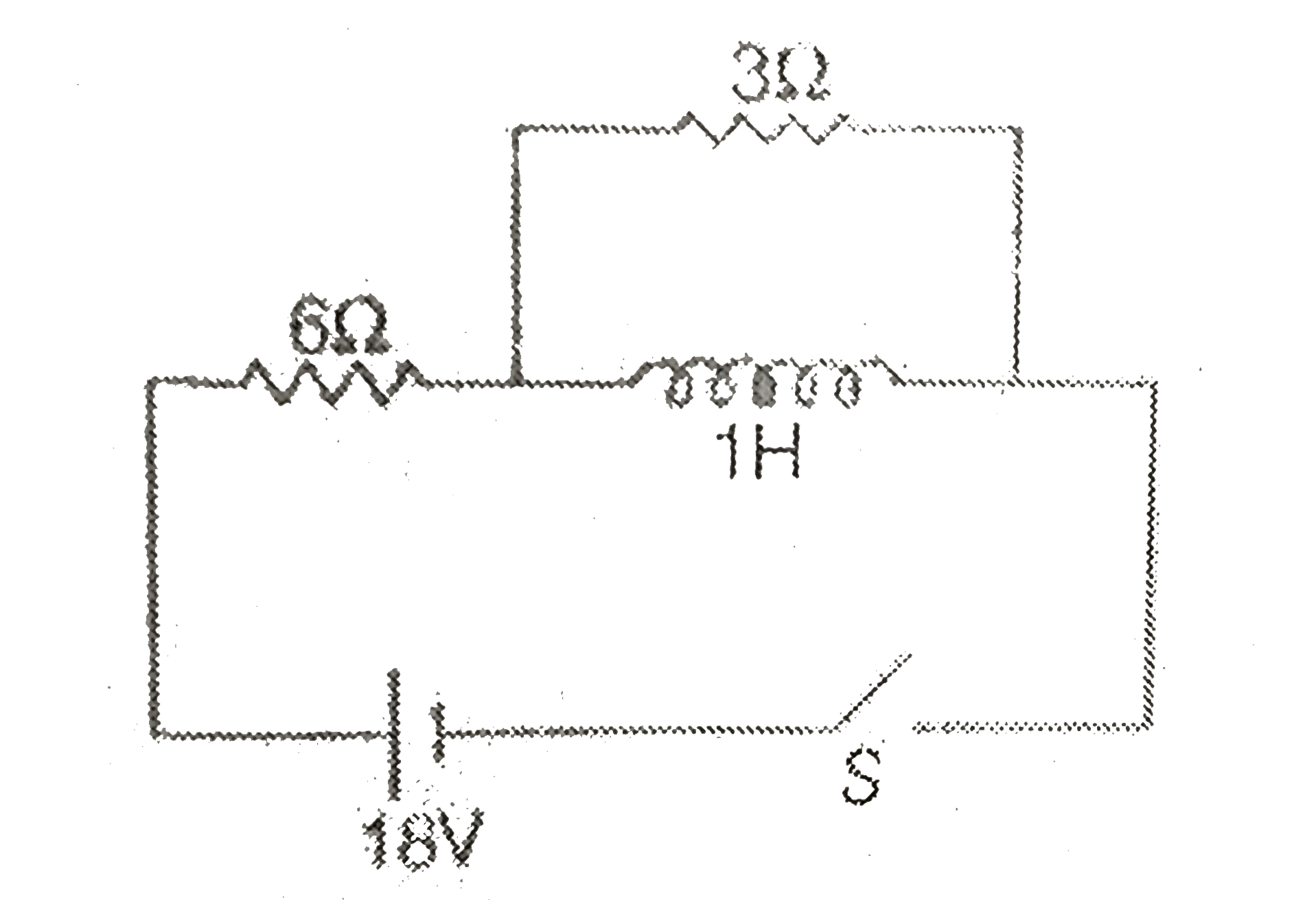
Switch is closed at t=0 then the current in the circuit at t=L2R is
_PHY_E06_157_Q01.png) View Solution
View Solution
Knowledge Check
- Question 1 - Select One
In the circuit as shown in the figure, switch S is added at t=0. Then:
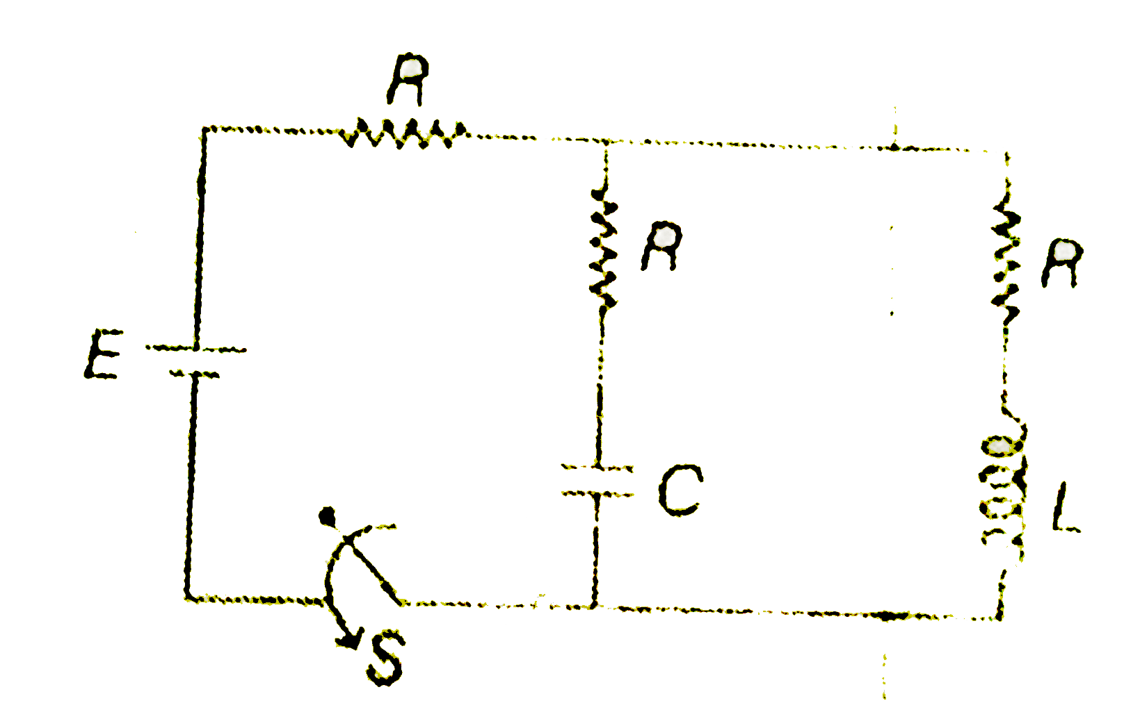 Aafter a long time interval potential differences across capacitor and inductor will be equalBafter a long time interval charge on a capacitor will be ECCafter a long time interval curent in the inductory will be E/RDafter a long time interval current through battery willl be same as the curren through it initially
 - Question 2 - Select One
In the circuit shown in the figure, if switches S1 and S2 have been closed for a long time, then charge on the capacitor.
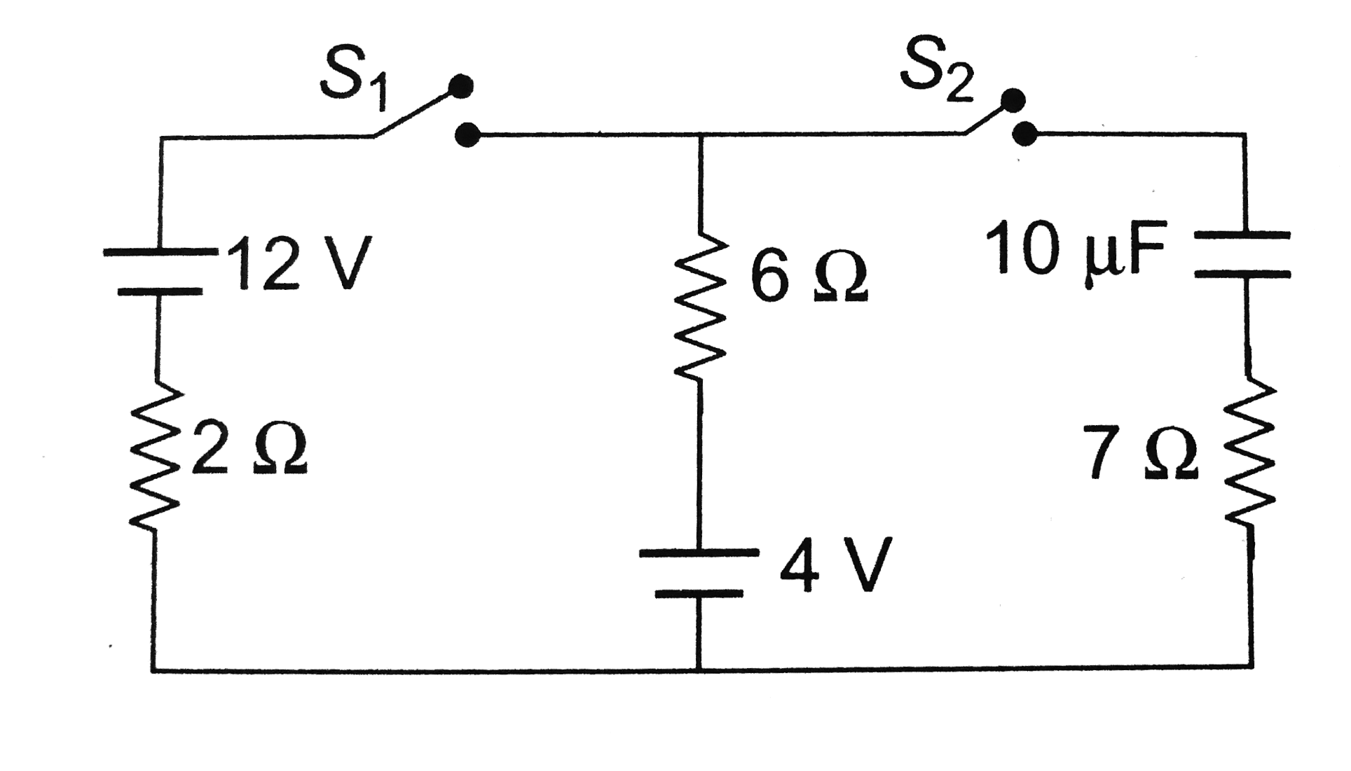 Ais 100μCBincreases to 200μC if one third of the gap of the capacitor's plates is filled with a dielectric (K=2) of same areaCboth (a) and (b) aboveDcharge on the capacitor remains unchanged if one third of the gap of the capacitor's plates is filled with a dielectric (K=2) of same area.
 - Question 3 - Select One or More
In the circuit shown in the figure, switch S is closed at time t=0. Select the correct statements.
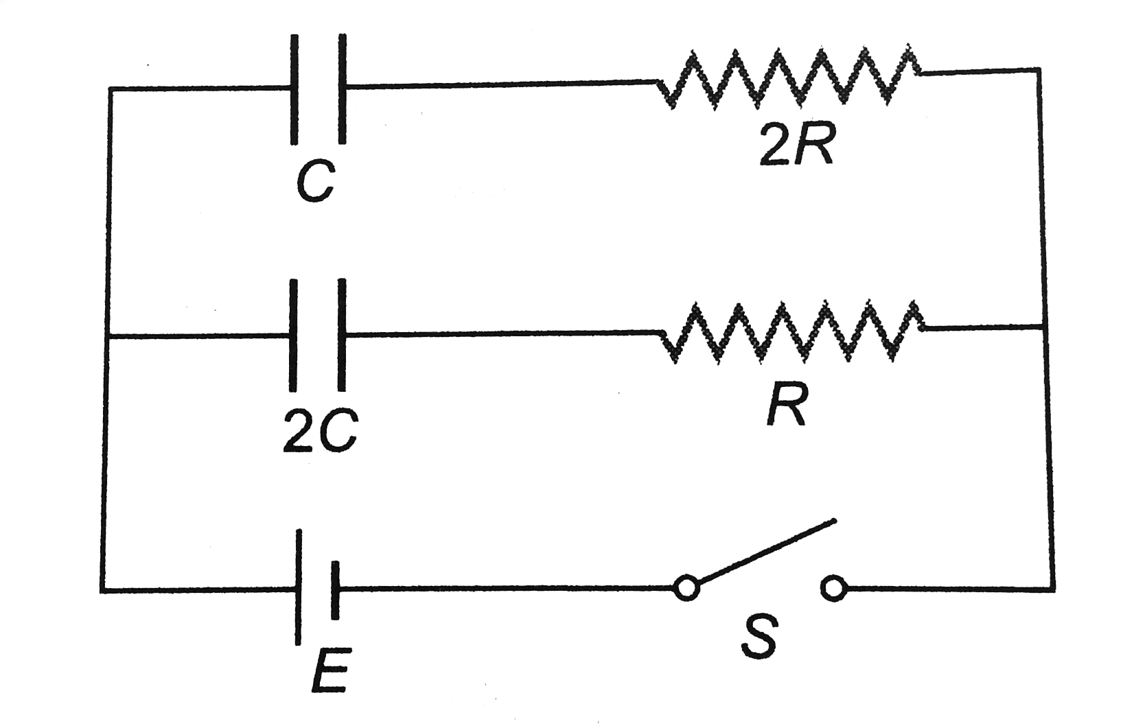 ARate of increase of charge is same in both the capacitorsBRatio of charge stored in capacitors C and 2C at any time t would be 1:2CTime constants of both the capacitors are equalDSteady state chares on capacitors C and 2C are in the ratio of 1:2
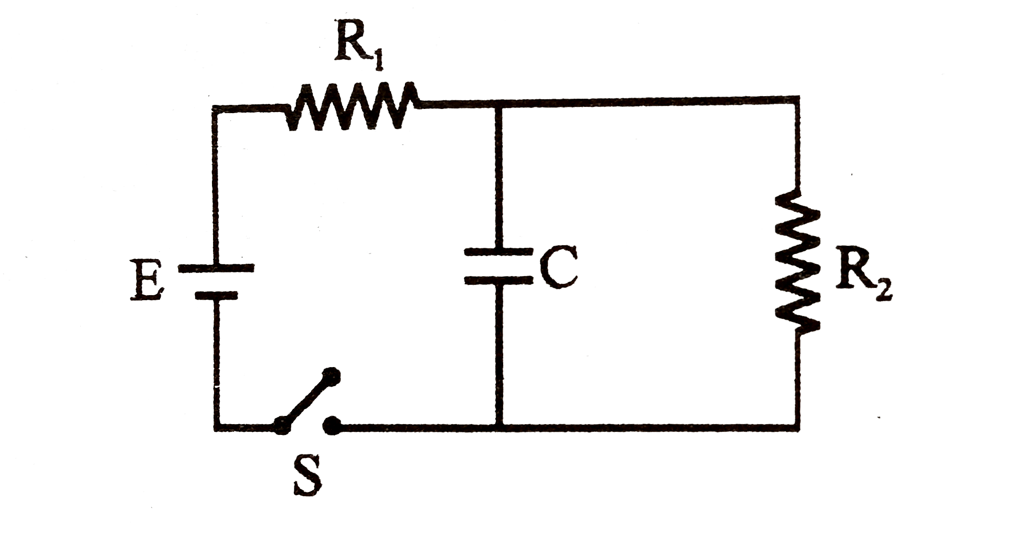
In the circuit shown. Initially the capacitor is uncharged. The switch S is closed at time t=0. Then
 View Solution
In the circuit shown in figure switch S is closed at time t=0
Current I from the battery at time t is given byView SolutionIn the circuit as shown in figure the switch is closed at t=0.
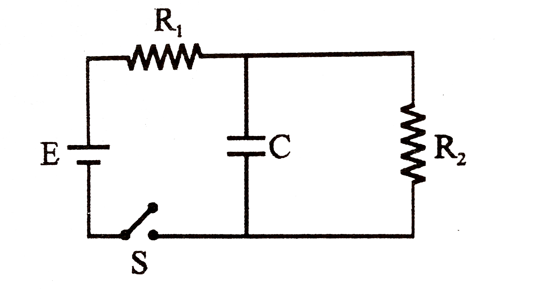
A long time after closing the switchView SolutionIn the circuit as shown in figure the switch is closed at t=0.
At the instant of closing the switchView SolutionIn the circuit shown in figure switch S is closed at time t=0, which statement is true after one time constant of L-R circuit?
 View Solution

