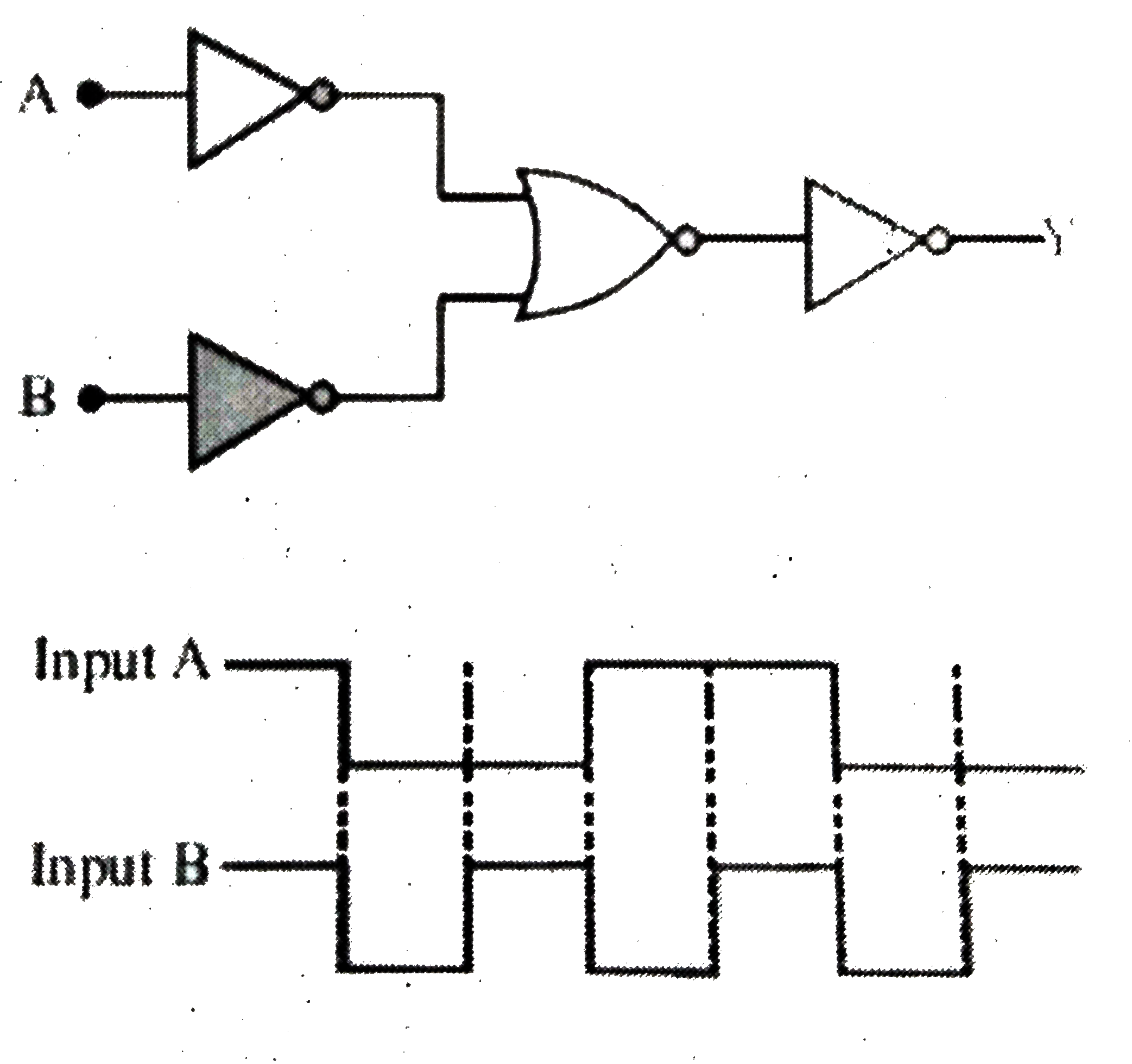
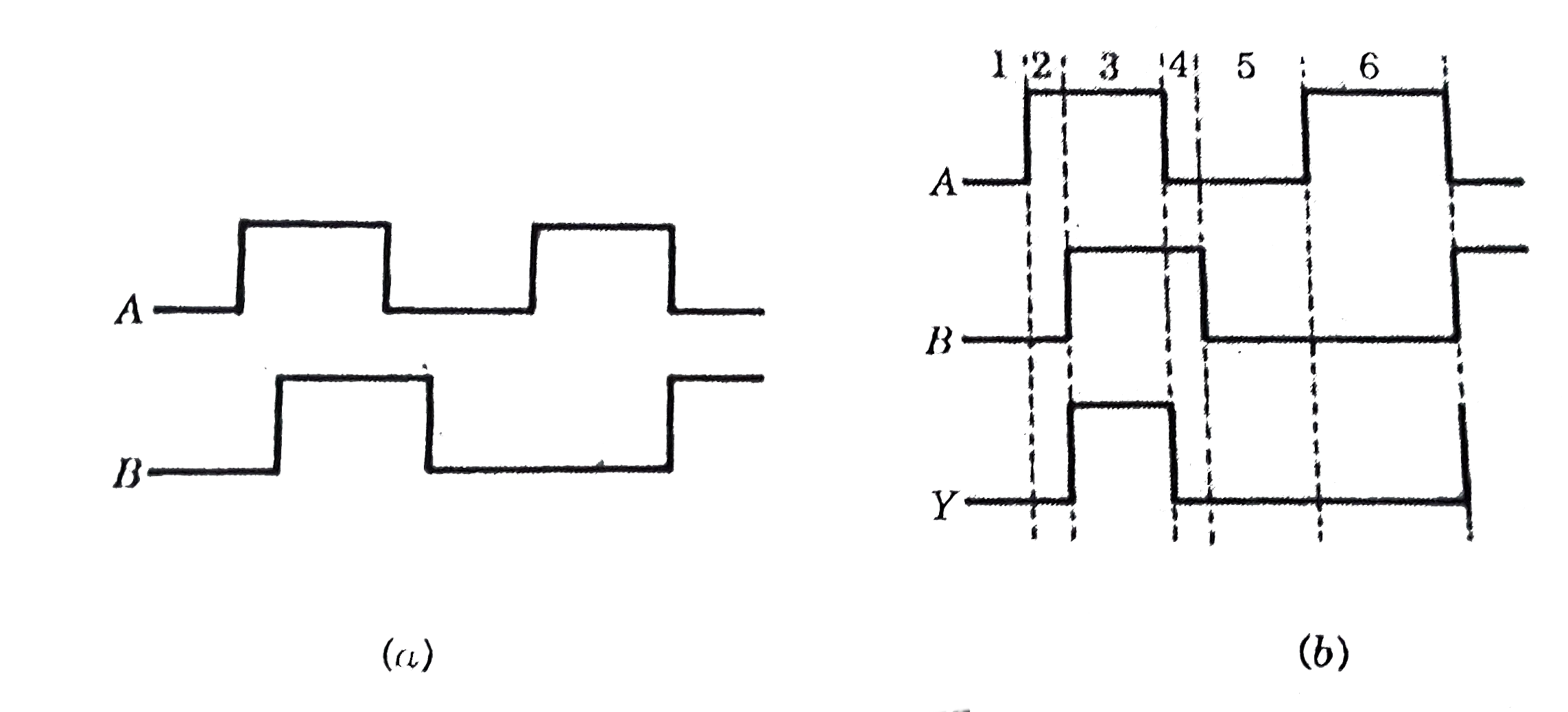
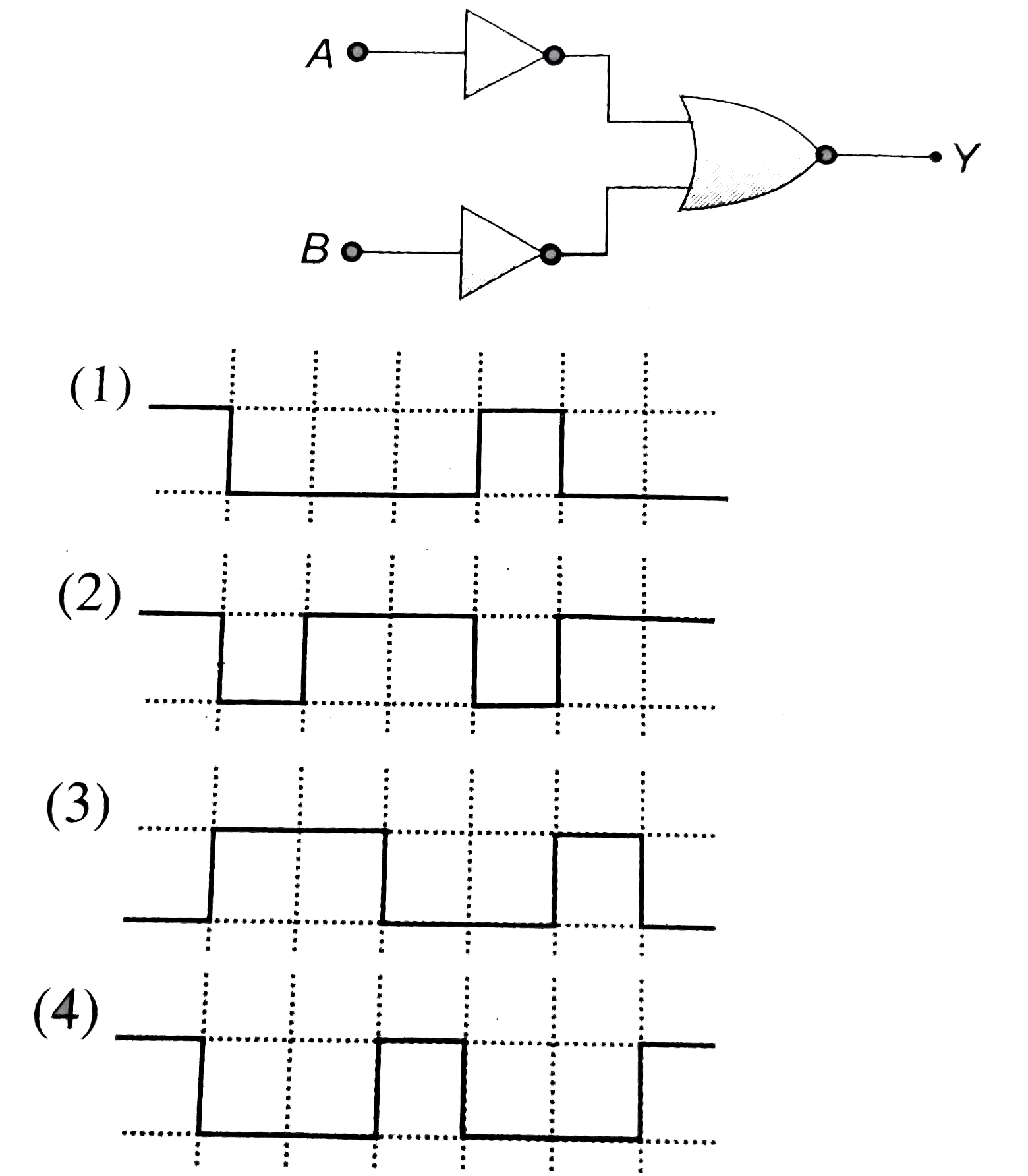
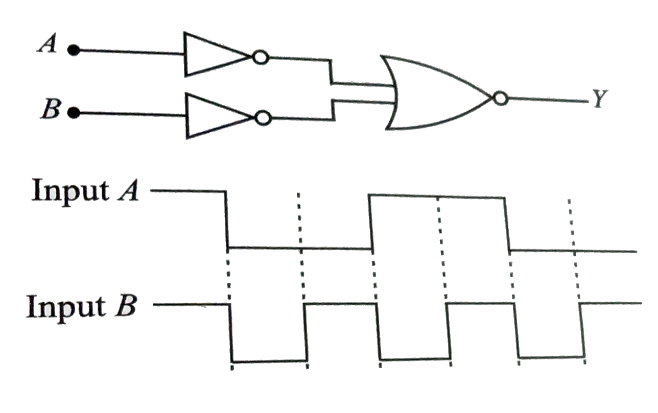
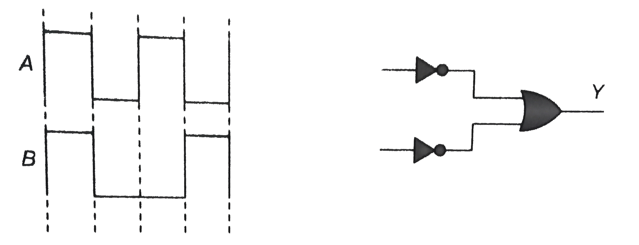
The logic circuit shown below has the input waveforms ‘A’ and ‘B’ as shown. Pick out the correct output waveform
A

B

C

D

Video Solution
Text Solution
The correct Answer is:A
Truth table
ABY111100010000
|
Topper's Solved these Questions
- SEMICONDUCTOR ELECTRONICSBOOK - NARAYNACHAPTER - SEMICONDUCTOR ELECTRONICSEXERCISE - EXERCISE -3
43 Videos
- SEMICONDUCTOR ELECTRONICSBOOK - NARAYNACHAPTER - SEMICONDUCTOR ELECTRONICSEXERCISE - EXERCISE-4
35 Videos
- SEMICONDUCTOR ELECTRONICSBOOK - NARAYNACHAPTER - SEMICONDUCTOR ELECTRONICSEXERCISE - EXERCISE -2 (H.W) (TRANSISTORS)
9 Videos
- SEMI CONDUCTOR DEVICESBOOK - NARAYNACHAPTER - SEMI CONDUCTOR DEVICESEXERCISE - Level-II (H.W)
36 Videos
- WAVE OPTICSBOOK - NARAYNACHAPTER - WAVE OPTICSEXERCISE - Exercise - 4 Polarisation
9 Videos
Similar Questions
Knowledge Check
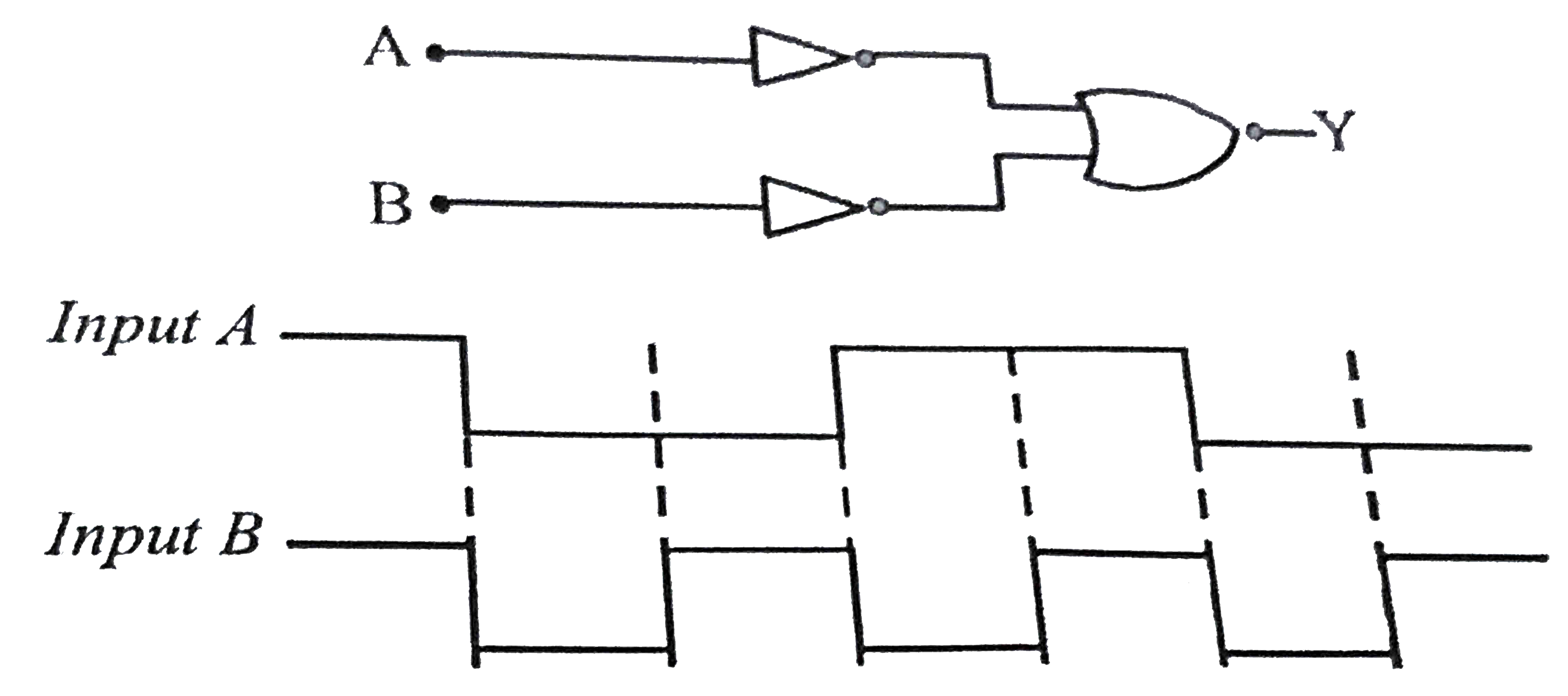
The logic circuit shown belows has the input waveforms 'A' and 'B' as shown. Pick out the correct output waveform
 A
A B
B C
C D
D
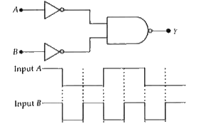
The logic circuit shown below has the inputs waveforms A and B as shown. Pick out the correct output waveform.
 A
A B
B C
C D
D
The logic circuit shown below has the input waveforms A and B as shown. Pick out the correct out put waveform.
 A
A B
B C
C D
D
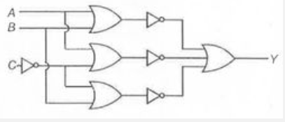
The output Y for logic diagram shown below is
View SolutionThe logic circuit shown below has the input waveform 'A' and 'B' as shown. Pick out the correct output waveform
_E01_490_Q01.png)
Output is :-
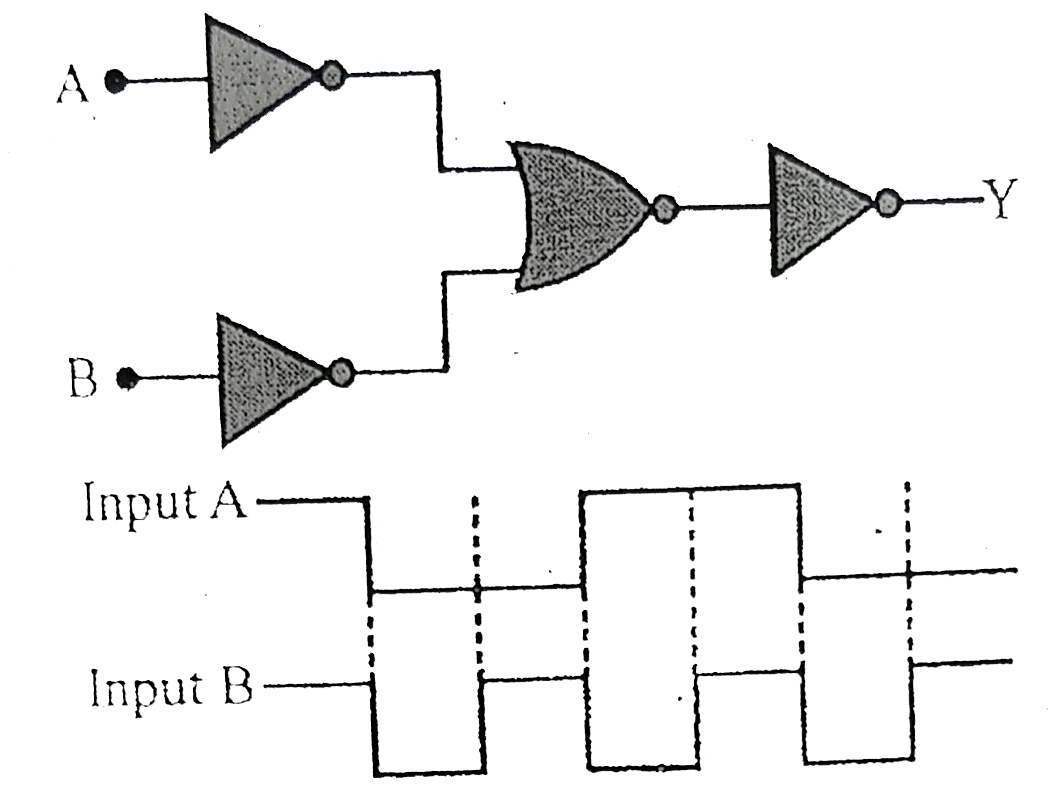
View SolutionThe logic circuit shown has the input waveforms 'A' and 'B' as shown. Pick out the CORRECT output waveform:-
View SolutionIn the given circuit as shown the two input waveform A and B are applied simultaneously. The resultant waveform Y is
View SolutionOutput of the circuit shown below will be

View Solution

