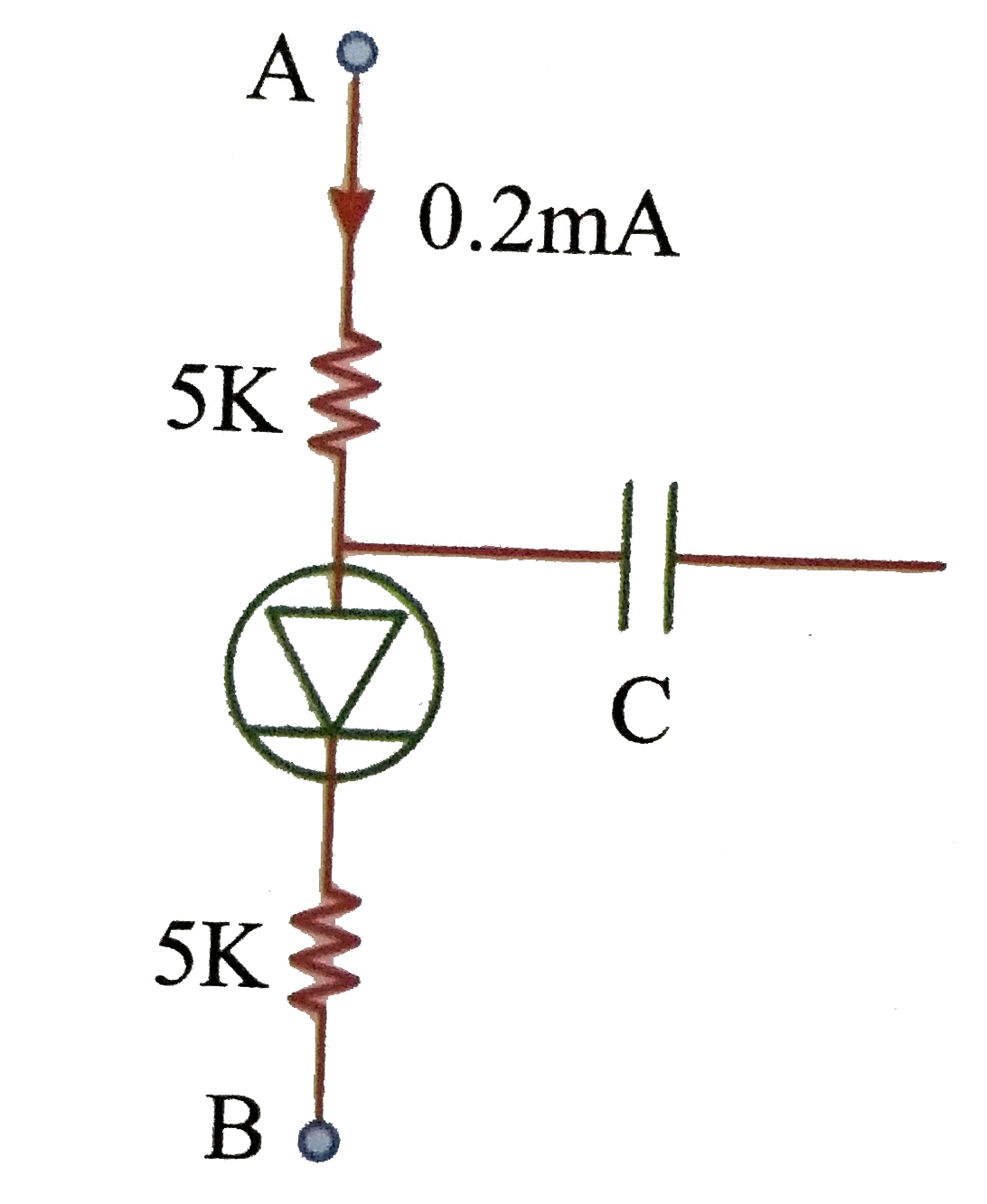
In the circuit shown(Fig.) if the diode forward voltage drop is 0.3V, the voltage difference between A and B is :
 .
.
A
1.3V
B
2.3V
C
0
D
0.5V
Video Solution
Text Solution
The correct Answer is:B
−0.2×10−3×5×10−3×5×103−VB=0
⇒VA−VB=2.3 volt
|
Topper's Solved these Questions
- SEMICONDUCTOR ELECTRONICSBOOK - NARAYNACHAPTER - SEMICONDUCTOR ELECTRONICSEXERCISE - EXERCISE -2 (C.W) (APPLICATIONS OF JUNCTION DIODE AS RECTIFIER)
1 Videos
- SEMICONDUCTOR ELECTRONICSBOOK - NARAYNACHAPTER - SEMICONDUCTOR ELECTRONICSEXERCISE - EXERCISE -2 (C.W) (TRANSISTORS)
11 Videos
- SEMICONDUCTOR ELECTRONICSBOOK - NARAYNACHAPTER - SEMICONDUCTOR ELECTRONICSEXERCISE - EXERCISE -2 (C.W) INTRINSIC, EXTRINSIC SEMICONDUCTONS)
2 Videos
- SEMI CONDUCTOR DEVICESBOOK - NARAYNACHAPTER - SEMI CONDUCTOR DEVICESEXERCISE - Level-II (H.W)
36 Videos
- WAVE OPTICSBOOK - NARAYNACHAPTER - WAVE OPTICSEXERCISE - Exercise - 4 Polarisation
9 Videos
Similar Questions
Knowledge Check
In the circuit shown in figure, if the A diode forward voltage drop is 0.3 V, the voltage difference between A and B is
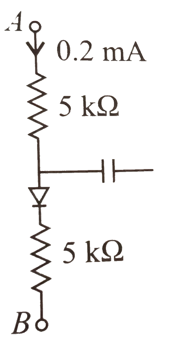 A1.3 VB2.3 VC0D0.5 V
In the circuit shown in figure, if the diode forward voltage drop is 0.3 V, then the voltage difference between A to B is,
 A1.3 VB2.3 VCzeroD0.5V
In the circuit, if the forward voltage drop for the diode is 0.5 V, the current will be:
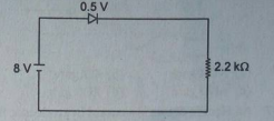 A3.4 mAB2 mAC2.5 mAD3 mA
In the circuit shown in figure, Voltage V0 is–
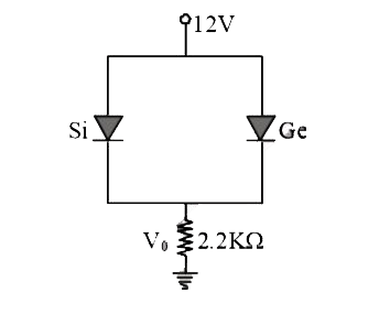
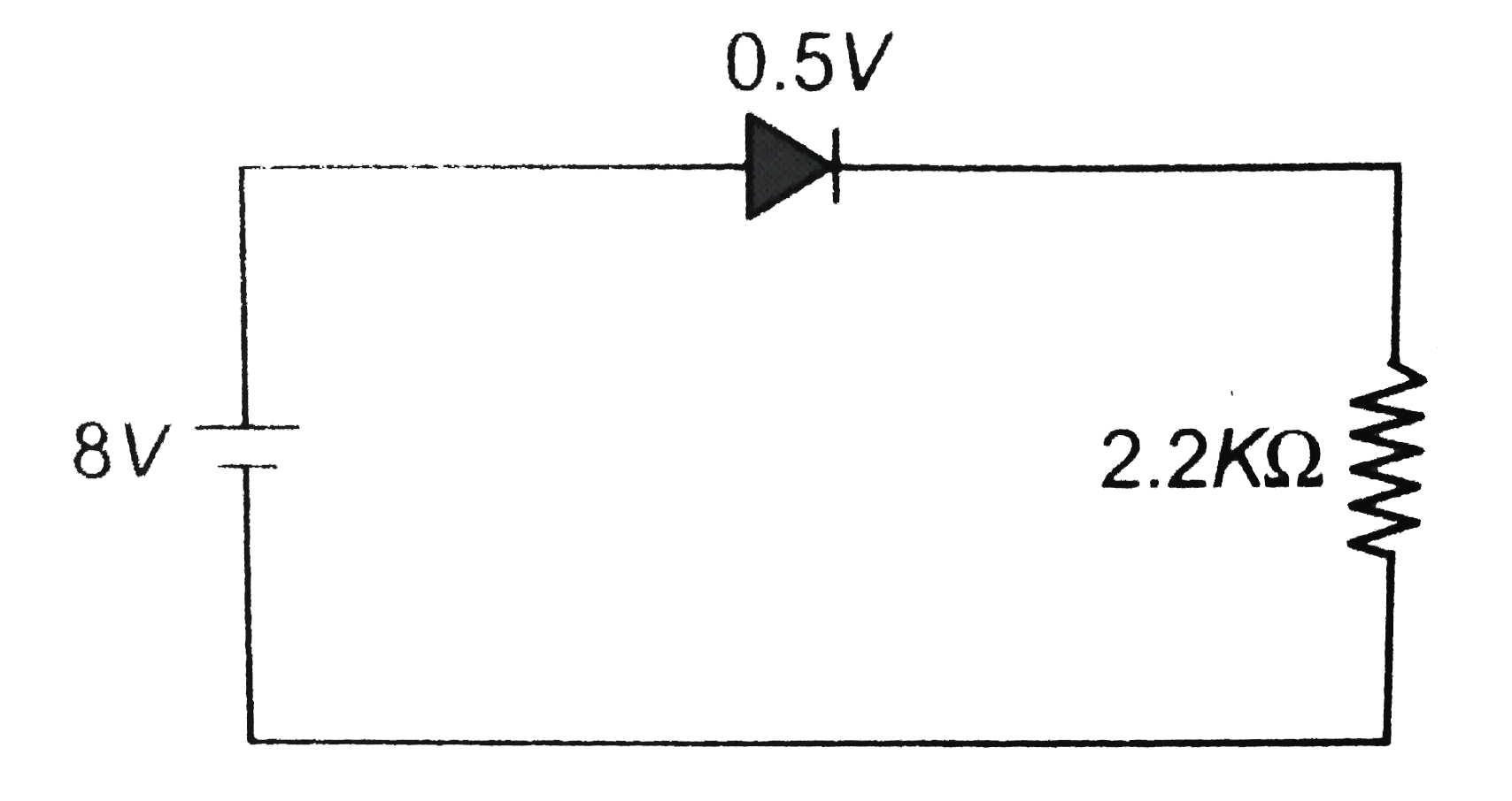
View SolutionIn the circuit, if the forward voltage drop for the diode is 0.5 V, the current will be:

View SolutionIn the circuit, if the forward voltage drop for the diode is 0.5V, the current will be
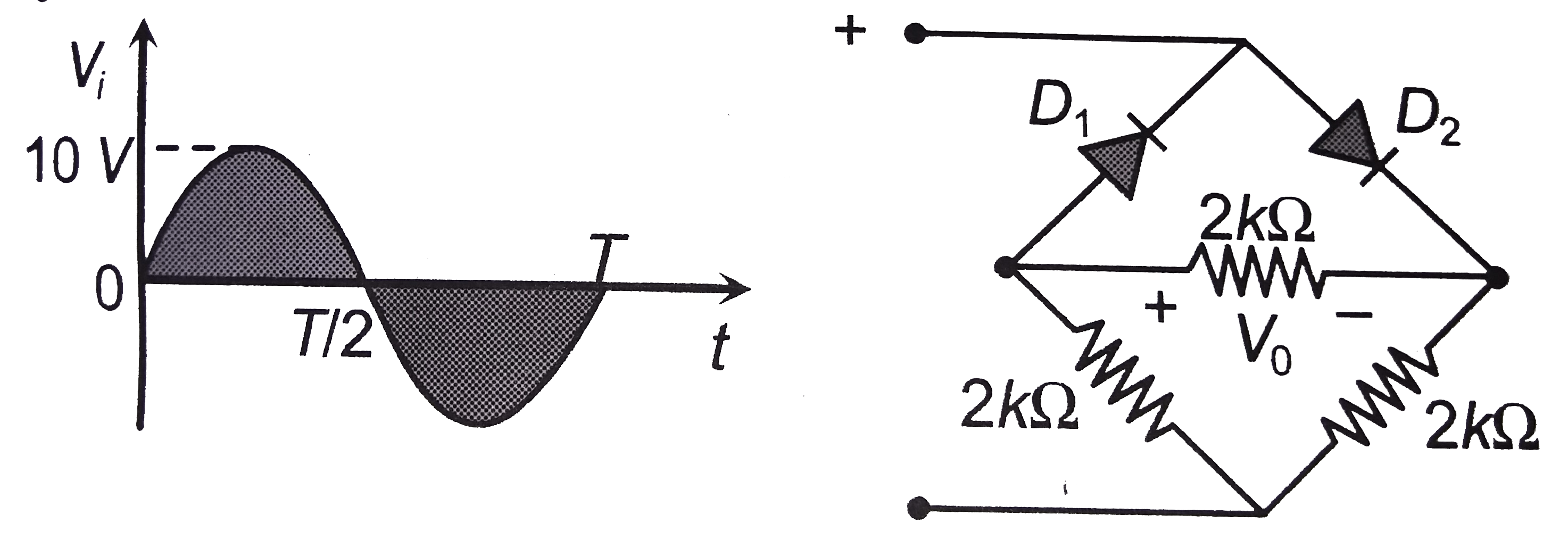
View SolutionIn the circuit shown in figure the maximum output voltage V0 is
View SolutionIn the circuit shown in figure, the final voltage drop across the capacitor C is :
View Solution

