The measurement of an unknown resistance R is to be carried out using Wheatstone bridge (see Fig. 2(EP).3). Two students perform an experiment in two way. The first student takes R2=10Ω and R1=5Ω. The other student takes R2=1000Ω and R1=500Ω. In the standard arm, both take R3=5Ω. Both find R=R2R1R3=10Ω within errors.
The errors of measurnment of the two students are the same.
Errors of measurnment do depend on the accuracy with which R2 and R1 can be measured.
If the students uses larger values of R2 and R1 the currents through the arms will be feeble. This will make determination of null point accurately more difficult.
Wheatstone bridge is a very accurate instrument and has no errors of measurnment.
The correct Answer is:B, C
Given, for first student,
R2=10Ω,R1=5Ω,R3=5Ω
For second student, R1=500Ω,R3=5Ω
Now, according to Wheatstone.s bridge rule,
R2R=R1R3⇒R=R3×R2R1

Now putting all the values in Eq. (i), we get R=10Ω for both students. Thus, we can analyse that the Wheatstone bridge is most sensitive and accurate if resistance are of same value.
Thus, the errors of measurnment of the two students depend on the accuracy and sensitivity of the brdge, which in turn depends on the accuracy with which R2 and R1 can be measured.
When R2 and R1 are larger, the currents through the arms of bridge is very weak. This can make the determination of null point accurately more difficult.
Similar Questions
Knowledge Check
In the given circuit, R1 = 10Ω R2=6Omega and E = 10V, then correct statement is
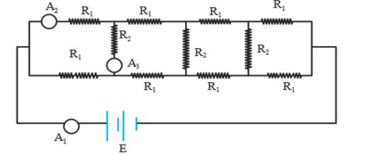 AEffective resistance of the circuit is 10ΩBR Reading of A1 is 1//2 amp.CReading of A2 is 1//2 ampDReading of A3 is 1//8 amp.
In the circuit shown in figure
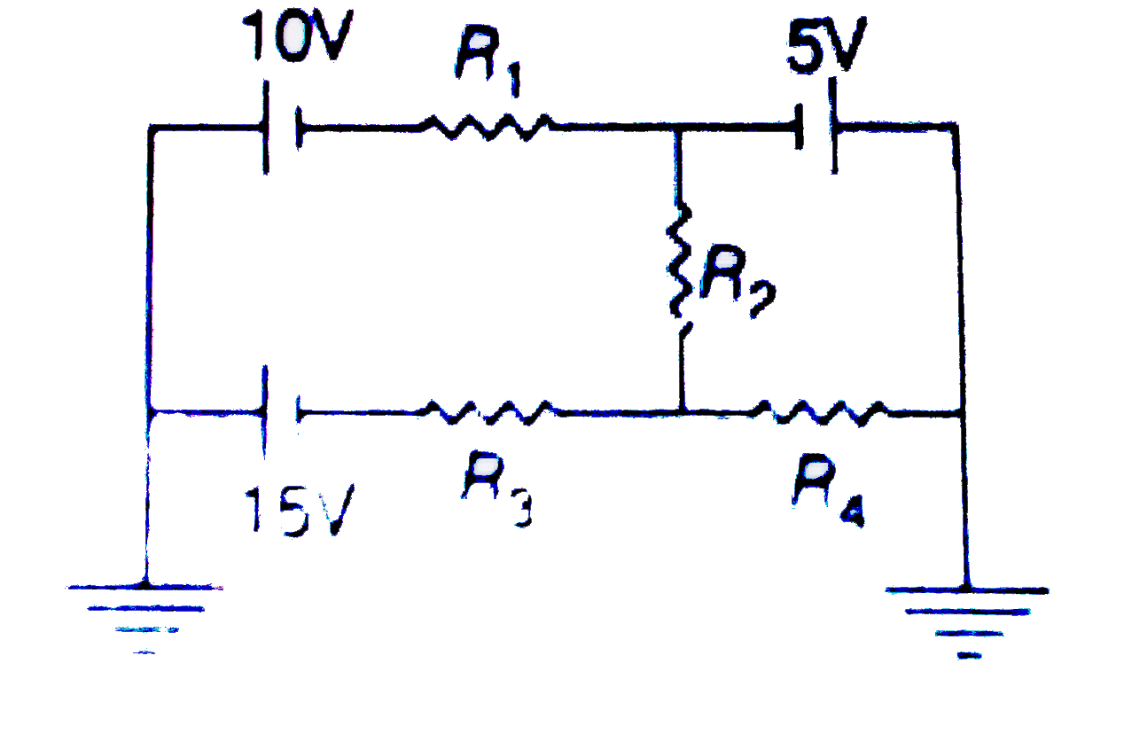
Current through R2 is zero if R4=2Ω and R3=4Ω In this caseACurrent through R3 is 2ABCurrent through R4 is 3ACboth (a) and (b) are correctDboth (a) and (b) wrongIn the circuit shown below E1=4.0V,R1=2Ω,E2=6.0V,R2=4Ω and R3=2Ω. The current I1 is
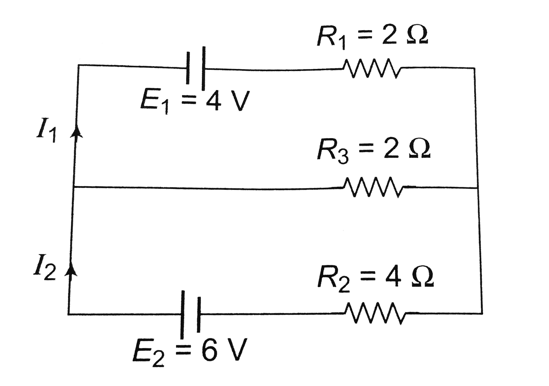 A1.6AB1.8AC1.25AD1.0A
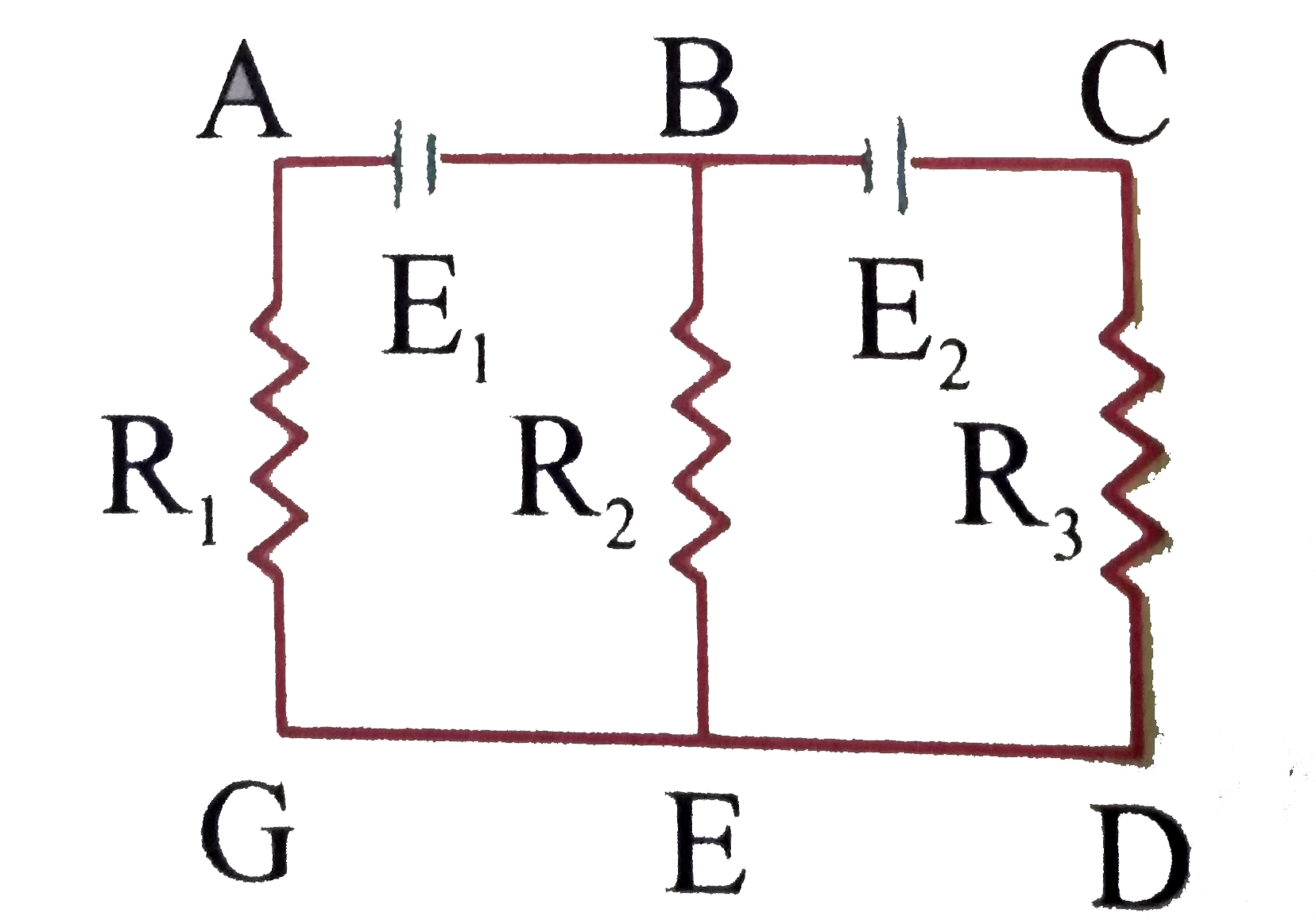
In the given circuit values are as follows
ε=2V,ε2=4V,R1=1Ω and R2=R3=1Ω.
Calculate the current through R1,R2 and R3
View SolutionFind the currents in the Y connection of 3 resistances R1=10Ω, R2=20Ω and R3=30Ω. When the terminals of R1 , R3 and R3 are maintained at potentials V1 = 10V, V2=6V and V3 = 15V.
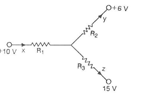
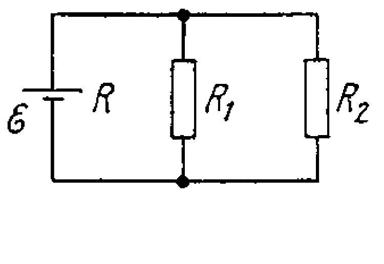
View SolutionIn the circuit shown in Fig. the emf of the sources is equal to ξ=5.0V and the resistances are equal to R1=4.0Ω and R2=6.0Ω. The internal resistance of the source equals R=1.10Ω. Find the currents flowing through the resistances R1 and R2.
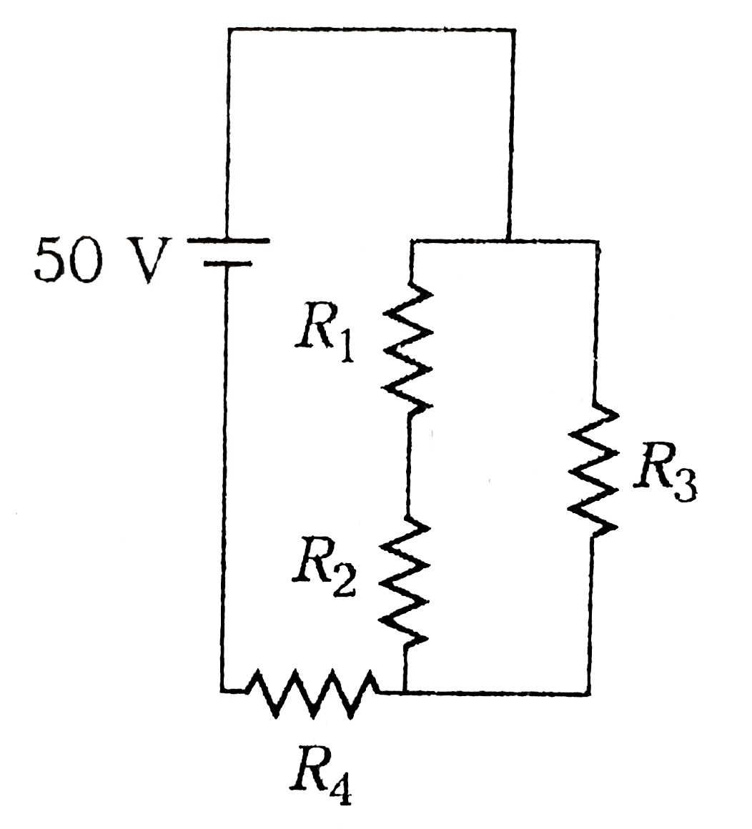
View SolutionThe potential difference in volt across the resistance R3 in the circuit shown in figure, is (R1=15Ω,R2=15Ω,R3=30Ω,R4=35Ω)
View SolutionIn the given figure, E=12V, R1=3Ω,R2=2Ω and r=1Ω. The choose the correct option/s
View Solution

