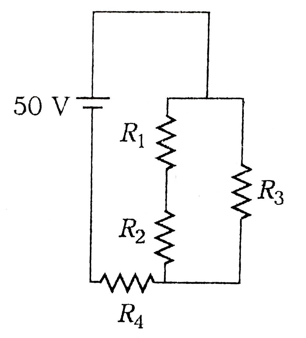
The potential difference in volt across the resistance R3 in the circuit shown in figure, is (R1=15Ω,R2=15Ω,R3=30Ω,R4=35Ω)
5
7.5
15
12.5
The correct Answer is:C
Step by step video, text & image solution for The potential difference in volt across the resistance R_(3) in the circuit shown in figure, is (R_(1)=15Omega,R_(2)=15Omega, R_(3)=30Omega, R_(4)=35Omega) by Physics experts to help you in doubts & scoring excellent marks in Class 12 exams.
Updated on:21/07/2023Topper's Solved these Questions
- CURRENT ELECTRICITYBOOK - DC PANDEYCHAPTER - CURRENT ELECTRICITYEXERCISE - B. Assertion and reason
18 Videos
- CURRENT ELECTRICITYBOOK - DC PANDEYCHAPTER - CURRENT ELECTRICITYEXERCISE - Match the columns
4 Videos
- CURRENT ELECTRICITYBOOK - DC PANDEYCHAPTER - CURRENT ELECTRICITYEXERCISE - Check point
70 Videos
- COMMUNICATION SYSTEMBOOK - DC PANDEYCHAPTER - COMMUNICATION SYSTEMEXERCISE - Subjective
11 Videos
- ELECTROMAGNETIC INDUCTIONBOOK - DC PANDEYCHAPTER - ELECTROMAGNETIC INDUCTIONEXERCISE - Medical entrances gallery
25 Videos
Similar Questions
Determine the voltage drop across the resistance R1 in the circuit given in Fig. 4.55 with ε=90V,R1=5kΩ,R2=5kΩ,R3=10kΩ and R4=10kΩ.
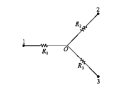
View SolutionFind the current flowing through the resistance R1 of the circuit shown in figure-3.103. the resistances are equal to R1=10Ω,R2=20Ω and R3=30Ω and the potentials of points 1,2 and 3 are given as V1=10V,V2=6V and V3=5V.
View Solution
Knowledge Check
In the circuit shown in figure
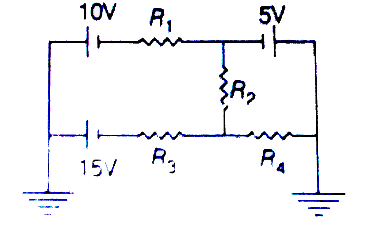
Current through R2 is zero if R4=2Ω and R3=4Ω In this caseACurrent through R3 is 2ABCurrent through R4 is 3ACboth (a) and (b) are correctDboth (a) and (b) wrong
Determine the voltage drop across the resistor R1 in the circuit given below with E = 65V, R_1 = 50 OmegaR_2 = 100 Omega, R_3 = 100 Omega, and R_4 300 Omega.
View SolutionFind the current flowing through the resistance R1 of the circuit shown in figure if the resistances are equal to R1=10Ω,R2=20ΩandR3,=30Ω and the potentials of the points 1, 2, and 3 are equal to φ1=10V,φ2=6Vandφ3=5V
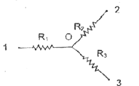
View SolutionFind the current flowing through the resistance R1 of the circuit shown in Fig. If the resistances are equal to R1=10Ω.R2=20Ω and R3=30Ω, and the potential of points 1,2 and 3 are equal to φ1=10V,φ2=6V, and φ3=5V

View SolutionFigure 27-11a shows a multiloop circuit containing one ideal battery and four resistances with the following values:
R1=20Ω,R2=20Ω,ε=12V,
R3=30Ω,R4=8.0Ω
(a) What is the current through the battery?
(b) What is the current i2 through R2?
(c) What is the current i3 through R3?
View Solution(a) Resistors given as R1,R2andR3 are connected in series to a battery V. Draw the circuit diagram showing the arrangement. Derive an expression for the equivalent resistance of the combination.
(b) If R1=10Ω,R2=20ΩandR3=30Ω, calculate the effective resistance when they are connected in series to a battery of 6 V. Also find the current flowing in the circuit.
View SolutionIn Fig. 27-43, the current in resistance 6 is i6=2.80A the resistances are R1=R2=R3=2.00Ω,R4=16.0Ω,R5=8.00ΩandR6=4.00Ω. Wat is the emf of the ideal battery?

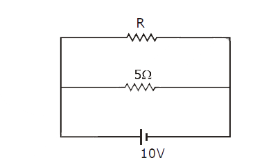
View SolutionThe power dissipated in the circuit shown in the figure is 30 W. The value of R is -
View Solution
