Obtain an expression for the impedance of a series LCR circuit. (using phasor diagram method). Solution in Kannada
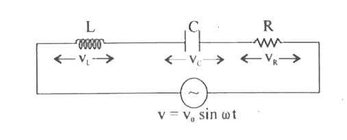
consider a resistance R, an inductor of self-inductance L and a capacitor of capacitance C connected in series across an AC source. The applied voltage is given by ,
v=v0sinωt …(1)

where, v is the instantaneous value, v0 is the peak value and ω=2πf , f being the frequency of AC.
If i be the instantaneous current at time t, the instantaneous votages across R,L and C are respectively iR, iXL and iXC. The vector sum of the voltage amplitudes across R,L , C equals the amplitude v0 of the voltage applied.
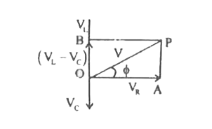
Let VR,VL and VC be the voltage amplitudes across R, L and C respectively and I0 the current amplitude . Then VR=i0R is in phase with i0 .
VL=i0XL=i0(ωL) leads i0 by 90∘ .
vC=i0XC=i0(1ωC) lags behind i0 by 90∘.
The current in a pure resistor is phase with the voltage , whereas the current in a pure inductor lags the voltage by π2 rad. The current in a pure capacitor leads the voltage by π2 rad.
For VL>VC , phase angle ϕ between the voltage and the current is positive.
From the right angled triangle OAP,

OP2=OA2+AP2=OA2+OB2(∵AP=OB)
V2=V2R+(VL−VC)2=(iR)2+(iXL−iXC)2
=i2(R2+(XL−XC)2)
i=V√R2+(XL−XC)2=VZ
and Z=√R2+XL−XC2
Where Z is the impedance of the circuit .
Phase angle between v & i.
tan ϕ=VL−VCVR=XL−XCRL
,ϕ=tan−1(XL−XCR)
Topper's Solved these Questions
- ANNUAL EXAM QUESTION PAPER -MARCH -2017 BOOK - SUBHASH PUBLICATIONCHAPTER - ANNUAL EXAM QUESTION PAPER -MARCH -2017 EXERCISE - PART -D
12 Videos
- ANNUAL EXAMINATION QUESTION PAPER (WITH ANSWER) MARCH 2018BOOK - SUBHASH PUBLICATIONCHAPTER - ANNUAL EXAMINATION QUESTION PAPER (WITH ANSWER) MARCH 2018EXERCISE - Part-C
11 Videos
Similar Questions
Deduce the condition for balance of a wheatstone's bridge using Kirchoffs rules .
View SolutionMention any three properties of an electric charge.
View Solutionप्रत्यावर्ती वोल्टता स्रोत के साथ सम्बद्ध श्रेणी LCR परिपथ के लिए फेजर चित्र खींचते हुए परिपथ की प्रतिबाधा का व्यंजक ज्ञात करें।
View SolutionObtain on expression for impedance and current in series LCR circuit. Deduce an expression for the resonating frequency of an LCR series reasonating circuit.
View SolutionIn a series LCR circuit connected to an ac source of voltage v=v_msinomegat , use phasor diagram to derive an expression for the current in the circuit. Hence obtain the expression for the power dissipated in the circuit.Show that power dissipated at resonance is maximum.
View SolutionObtain an expression for the impedance of a series LCR circuit. (using phasor diagram method).
View Solutionश्रेणी LCR परिपथ की प्रतिबाधा के लिए व्यंजक लिखिए।
View SolutionWith the help of a phasor diagram find an expression for impedance (Z) in a series L-C-R circuit.
View SolutionDerive an expression for the impedance of a series LCR, circuit, when an AC voltage is applied to it.
View SolutionWith the help of phasor diagram derive an expression for impedance in LCR circuit.
View SolutionWith the help of phasor diagram derive an expression for impedance in LCR circuit.
View SolutionUsing phasor diagram, derive an expression for impedance of an a.c. circuit containing LCR in series.
View SolutionFind an expression for impedance of L.C.R. se ries circuit using phasor diagram.
View SolutionA series LCR AC circuit has great practical importance. It is used for tuning radio, TV, wireless sets etc. : Obtain an expression for current in a series LCR ac circuit using phasor diagram.
View SolutionDerive an expression for the impedance of a series LCR, circuit, when an AC voltage is applied to it.
View Solution
