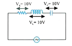
In the L-C-R circuit as shown in figure,
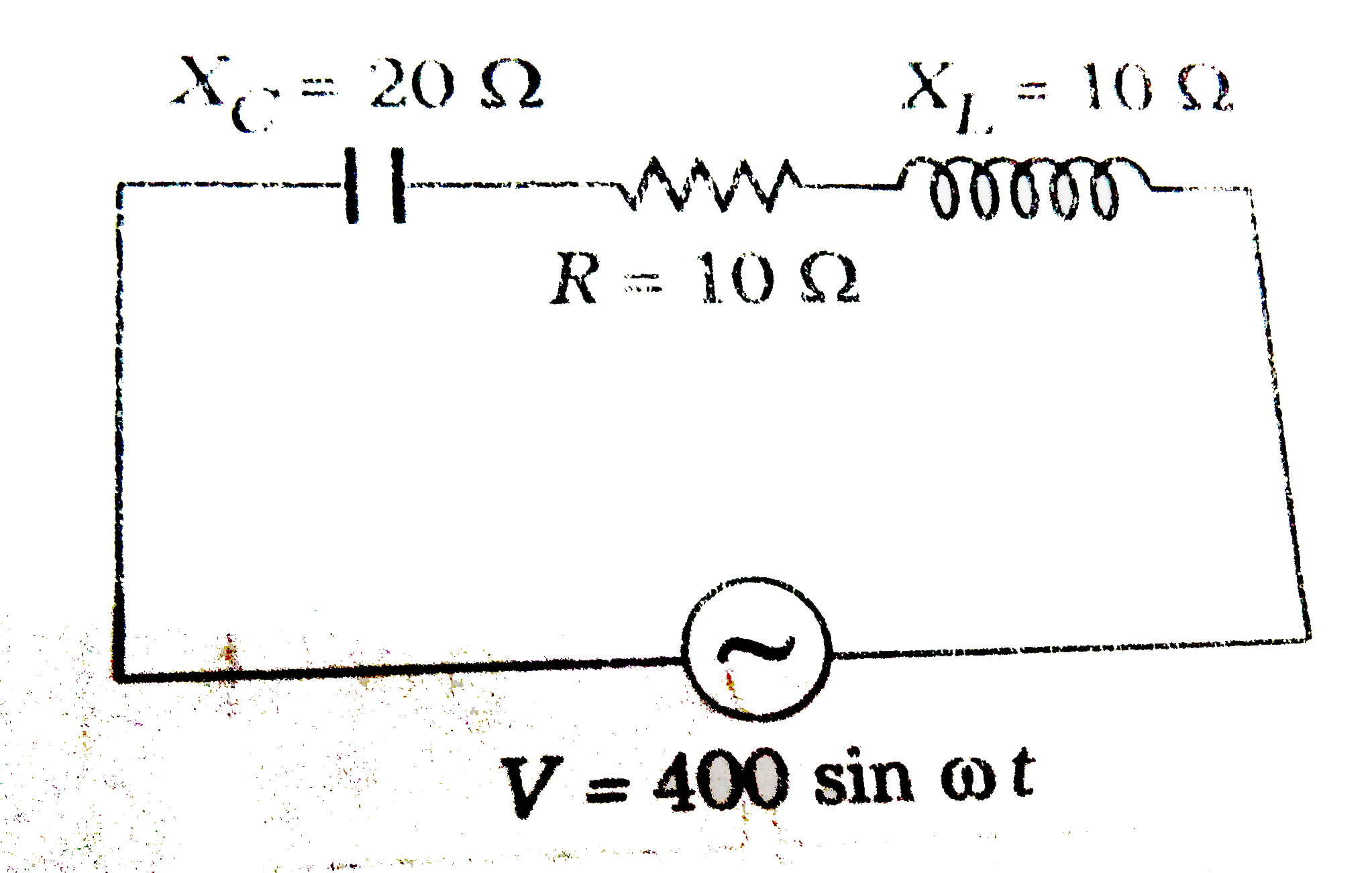
Current will lead the voltage
Runs value of current is 20 A
Power factor of the circuit is 1√2
Voltage drop across resistance is 200 V
The correct Answer is:A, B, C, D
(a,b,c,d) XC>XL, Hence, current will lead the voltate.
Z=√R2+(XC−XL)2=10√2Ω
∴Irms=VrmsZ=400√210√2=1√2
VR=IrmsR=(20)(1)=200V
Similar Questions
Knowledge Check
In the L-R circuit as shown in figure, potential difference across the resistance at some instant is 4 V. Then
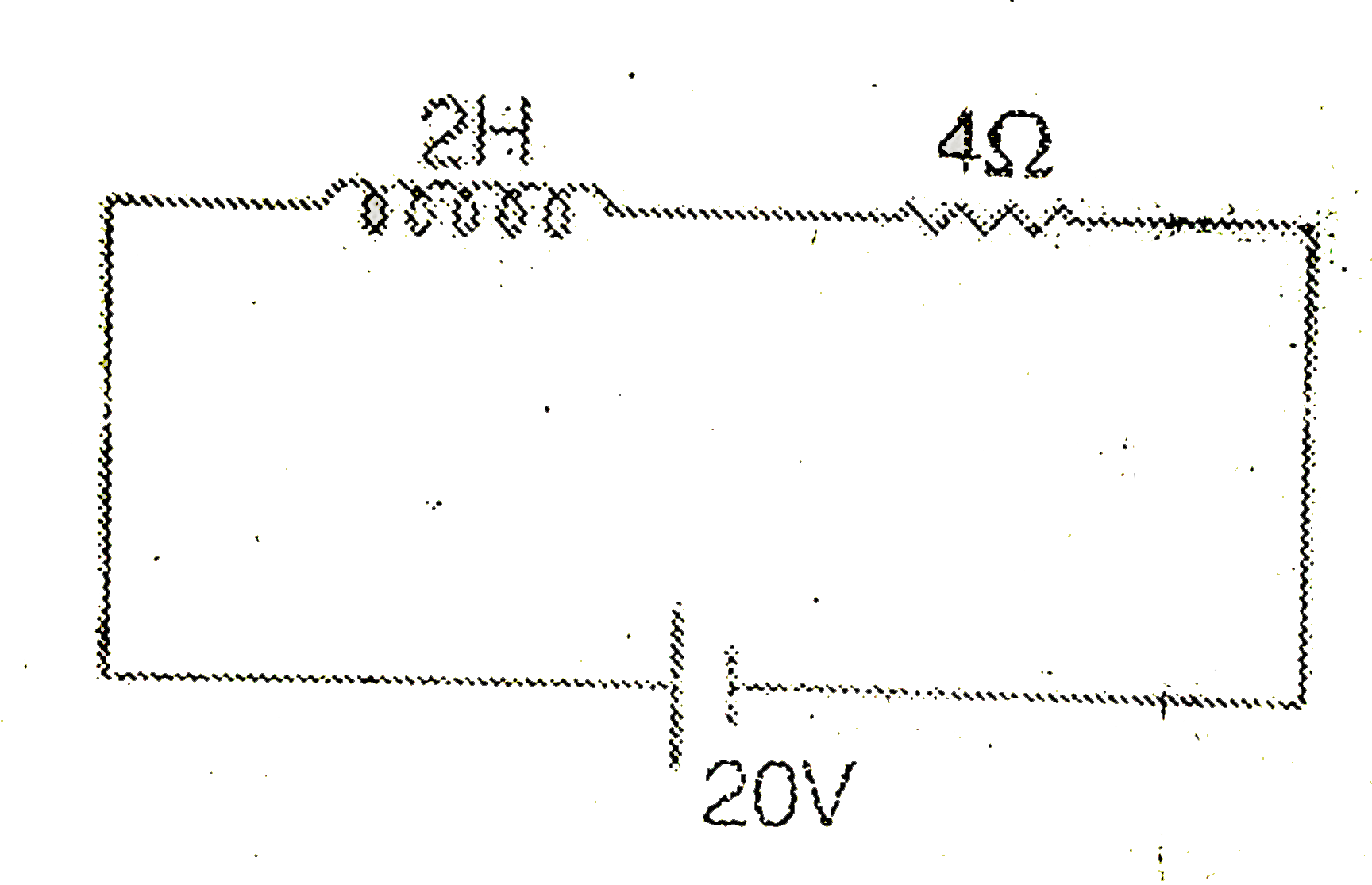 Acurrent is increasing at a rate of 8A/s at this instantBpower supplied by the battery at this instant is 20WCpower stored in the magnetic field at this instant is 16WDcurrent in the circuit at this instant is 1A
For series L-C-R circuit shown in the figure, the readings of V1 and V3 are same and each equal to 100 V .Then
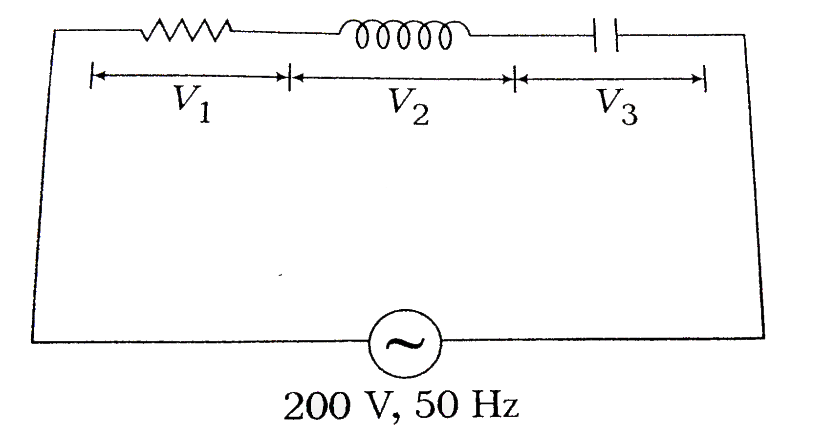 Athe reading V2 is 200 VBthe reading of V2 is 0Cthe circuit is in resonant mode and resonant frequency is 50 HzDthe inductive and capacitive reactance are equal
An inductor L and a capacitor C are connected in the circuit as shown in the figure. The frequency of the power supply is equal to the resonant frequency of the circuit. Which ammeter will read zero ampere
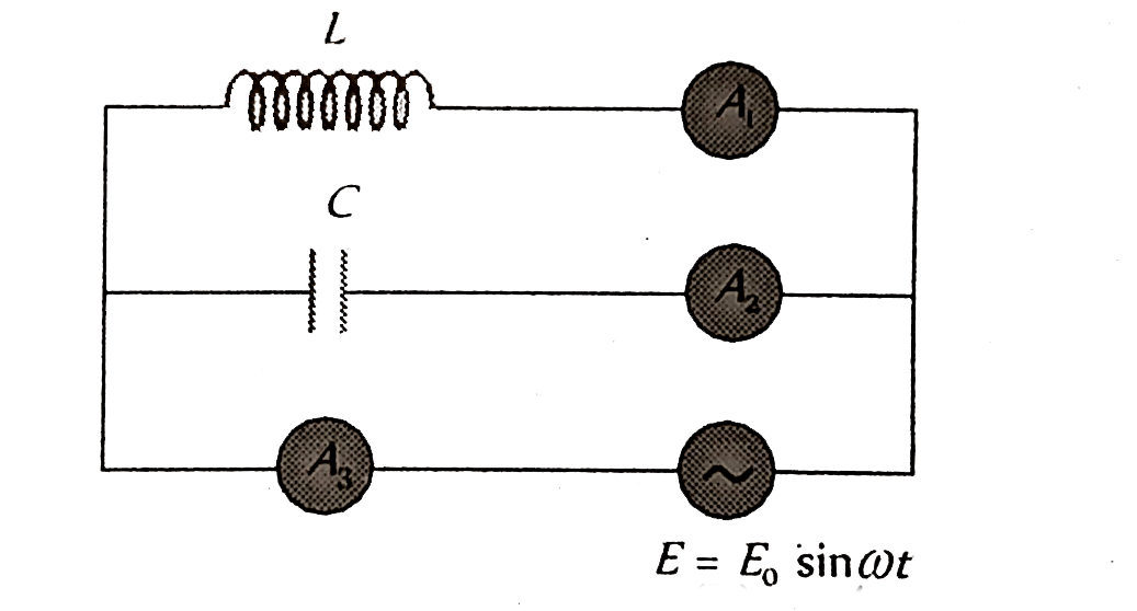 AA1BA2CA3DNone of these
In serial L-C-R circuit as shown in figure. The potential difference across A & B is
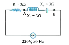
View SolutionIn the series LCR circuit as shown in the figure, the heat developed in 80s is x joule and amplitude of wattless current is y ampere. Find xy100.
'(##CEN_KSR_PHY_JEE_C24_E01_019_Q09##)'
View SolutionIn an AC circuit as shown in the figure, the source is of r.m.s voltage 200 V and variable frequency. At resonance, the circuit
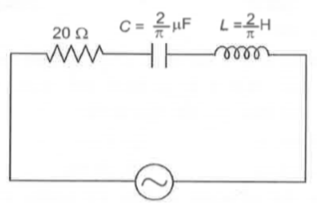
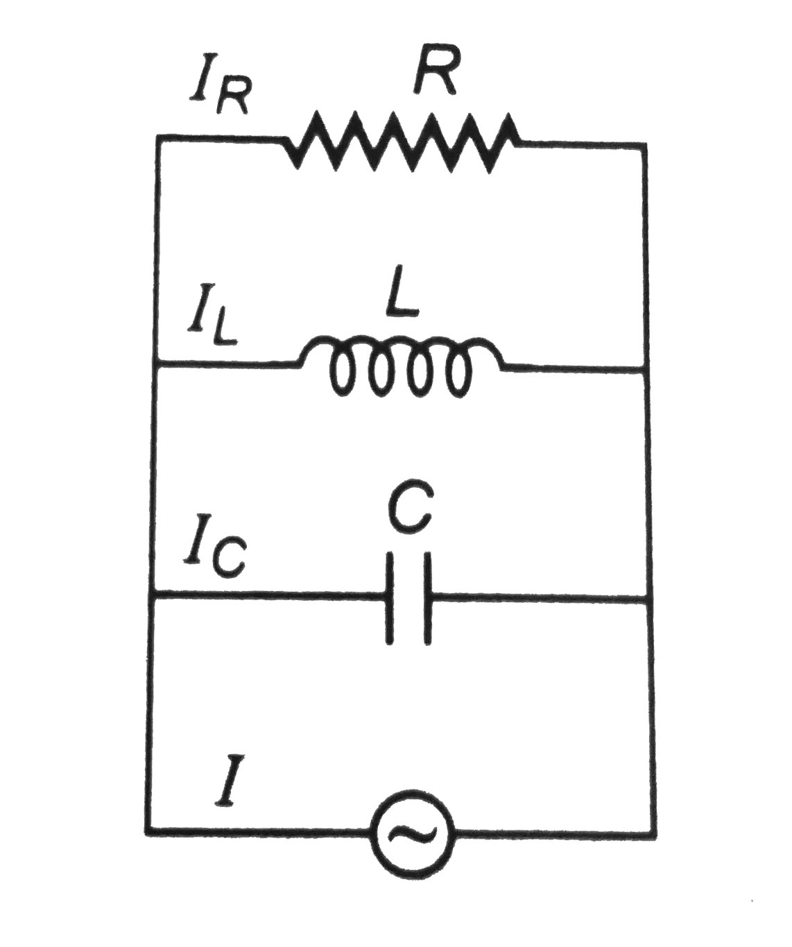
View SolutionIn a parallel L−C−R circuit as shown in figureure if IR,IL,IC and I represent the rms values of current flowing through resistor, capacitor and the source, then choose the appropriate correct answer.
 .
.
View SolutionIn a series L-C-R circuit shown in the figure , what is the resonance frequency and the current at the resonating frequency?
View Solution


