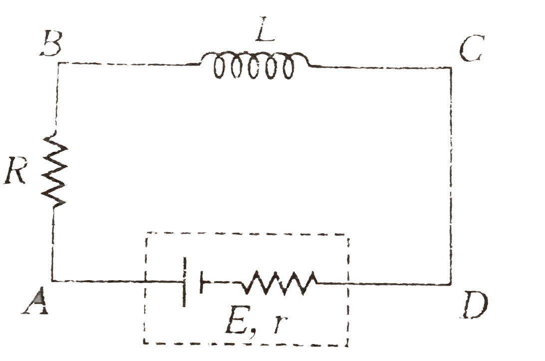
In the circuit diagram shown in Figure, R=10Ω,L=l5H,E=20v,i=2A. This current is decreasing at a rate of −1.0A/s. Find Vab at this instant.

Potential difference across inductor is given as
VL=Ldidt=(5)(−1.0)=−5V
Now, using Kirchhoff's second law, Va−iR−VL−E=Vb
∴ Vab=Va−Vb=E+iR+VL
=20+(2)(10)−5=35V
Note In the above example, as the current is decreasing, the inductor can be replaced by a source of emf e=∣∣∣l.didt∣∣∣=5 V in such a manner that this emf supports the decreasing current, or it sends the current in the circuit in the same direction as the existing current. So, positive termianl of this source is towards b. Thus, the given circuit can be drawn as

Topper's Solved these Questions
- ELECTROMAGNETIC INDUCTIONBOOK - DC PANDEYCHAPTER - ELECTROMAGNETIC INDUCTIONEXERCISE - Example Type 1
3 Videos
- ELECTROMAGNETIC INDUCTIONBOOK - DC PANDEYCHAPTER - ELECTROMAGNETIC INDUCTIONEXERCISE - Example Type 2
2 Videos
- CURRENT ELECTRICITYBOOK - DC PANDEYCHAPTER - CURRENT ELECTRICITYEXERCISE - Medical entrances gallery
97 Videos
- ELECTROMAGNETIC WAVESBOOK - DC PANDEYCHAPTER - ELECTROMAGNETIC WAVESEXERCISE - Sec C
22 Videos
Similar Questions
Knowledge Check
In the circuit diagram shown, R=10ω,L=5mH,E=10 V and i=1A. The current is decreasing at the reate of 103A/S. Then (VA−VB)at this instant is :
 A10VB15VC20VD25V
In the circuit shown in figure L=10H,R=5Ω,E=15V. The switch S is closed at t=0. At t=2s the current in the circuit is
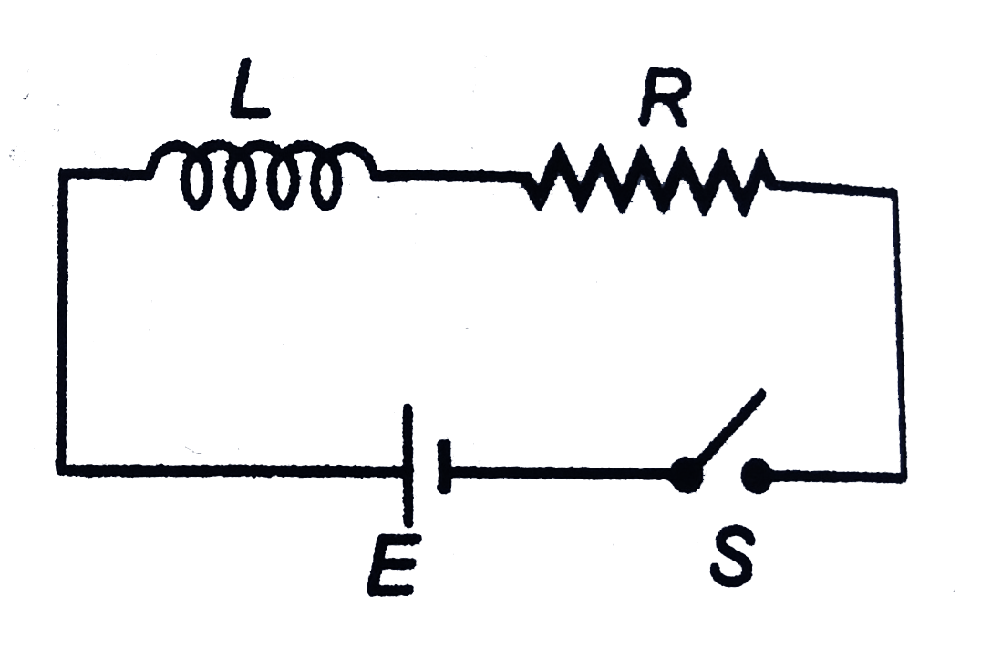 A3(1−1e)AB3(1−1e2)AC3(1e)AD3(1e2)A
In an L-C circuit shown in figure
C=1F, L=4H
At time t=0, charge in the capacitor is 4C and it is decreasing at a rate of √5C/s
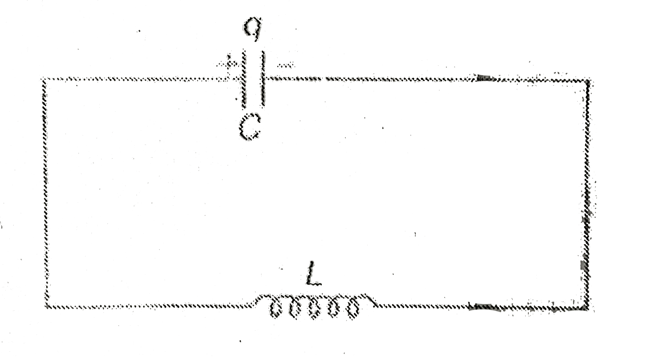
Choose the correct option
 Amaximum current in the circuit is 4ABWhen current is half its maximum value, charge in capacitor is less than is maximum valueCBoth a and b are correctDBoth a and b are wrong
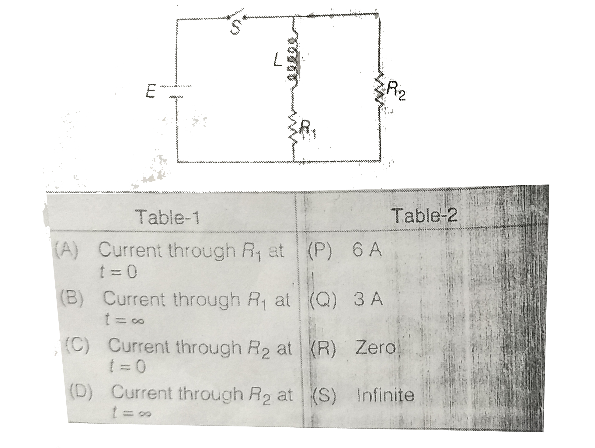
In the circuit diagram shown in Figure E=18V , L=2H, R1=3Ω,R2=6Ω. Switch S is closed at t=0 Match the following:
View SolutionA part of a complete circuit is shown in the figure . At some instant the value of current I is 1 A and it is decreasing at a rate of 102As−1 . The value of the potential difference VP−VQ, (in volts) at that instant , is ____________.

View SolutionIn the circuit shown in figure, E = 10 V, r = 1Ω,
R = 4Ω and L = 5H. The circuit is closed at time t = 0.
Then, match the following two columns.
Column IColumn IIA.VAD at t = 0p4VB.VBC at t = 0q8VC.VAB at t =∞r.0VD.VAD at t=∞s.10V
View SolutionIn the circuit (Fig.) what is potential difference VB−VA (in V) when current I is 5A and is decreasing at the rate of 103As−1

View SolutionIn the L-R circuit as shown in figure, potential difference across the resistance at some instant is 4 V. Then
View Solution


