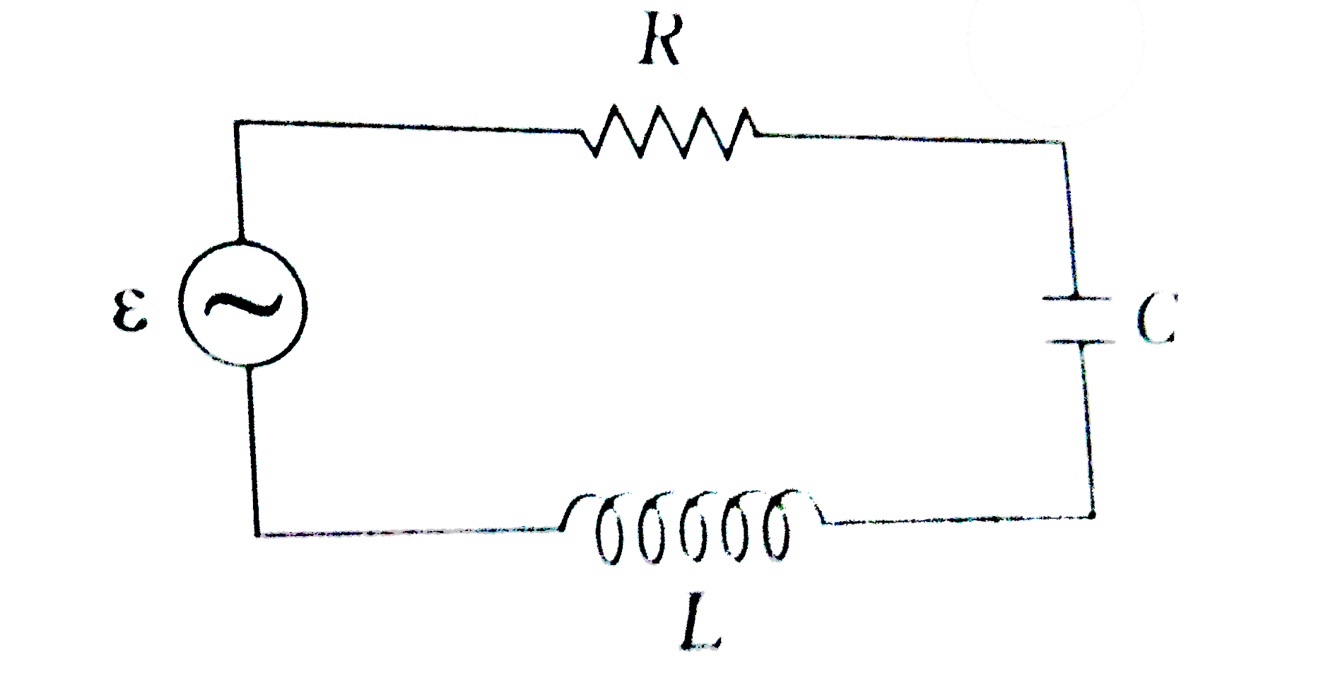
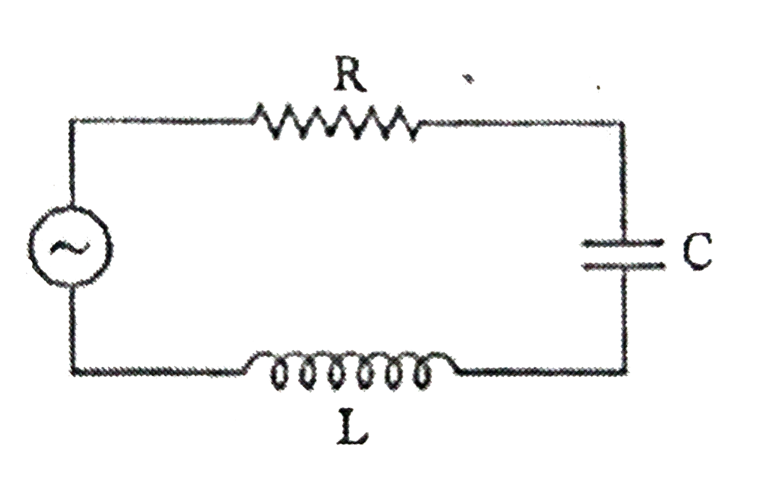
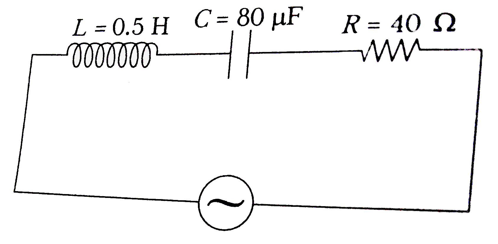
Figure shows a series LCR circuit connected to a variable frequency 230 V source.

The source frequency which drives the circuit the circuit in resonance is
4 Hz
5 Hz
6 Hz
8 Hz
The correct Answer is:D
Here, L=5H,C=80μF=80×10−6F,R=40Ω
Vrms=230V
The resonannt angular frequency is
ωr=1√LC=1√5×80×10−6=50 rad s−1
∴υr=ωr2π=502π=8Hz
Topper's Solved these Questions
- ALTERNATING CURRENT BOOK - NCERT FINGERTIPSCHAPTER - ALTERNATING CURRENT EXERCISE - Power In Ac Circuit
13 Videos
- ALTERNATING CURRENT BOOK - NCERT FINGERTIPSCHAPTER - ALTERNATING CURRENT EXERCISE - Lc Oscillations
9 Videos
- ALTERNATING CURRENT BOOK - NCERT FINGERTIPSCHAPTER - ALTERNATING CURRENT EXERCISE - Ac Voltage Applied To A Capacitor
12 Videos
- ATOMS BOOK - NCERT FINGERTIPSCHAPTER - ATOMS EXERCISE - Assertion And Reason
15 Videos
Similar Questions
Knowledge Check
In series LCR circuit at resonance
APower factor is zeroBPower developed across the resistor is maximumCPower developed across the inductor is zeroDBoth (2) & (3)In series LCR circuit at resonance,
Acurrent is maximum and impedance is maximumBcurrent is maximum and impedance is minimumCcurrent is minimum and impedance is maximumDcurrent is minimum and pmpedance is minimumIn series LCR circuit at resonance,
Acurrent is maximum and voltage is minimumBcurrent is maximum and voltage is maximumCcurrent is minimum and voltage is maximumDcurrent is minimum and voltage is minimum
Figure here, shows a series L-C-R circuit connected to a variable frequency 230 V source. L = 5.0H, C = 80μF and r =40Ω
(a) Determine the source frequency which drives the circuit in resonance.
(b) Obtain the impedance of the circuit and the amplitude of current at the resonating frequency.
(c) Determine the rms potential drops across the three elements of the circuit. show that the potential drop across the L-C combination is zero at the resonating frequency.

View SolutionA series LCR circuit with L=4.0h,C=100μF and R=60Ω is connected to a varialbe frequency 240 V source. Calcalate
(i) angular frequency of the source which drives the circuit in resonace,
(ii) current at the resonating frequency,
(iii) rms potential drop across the inductro at resonance.
View SolutionThe figure shows a series LCR circuit with L=10.0H2,C=40μF,R=60Ω connected to a variable frequency 240 V source. Calculate
(i) The angular frequency of the source which drives the circuit at resonance.
(ii) The current at the resonating frequency.
(iii) The rms potential drop across the capacitor at resonance.

View SolutionIn a series LCR circuit, at resonance the
View SolutionIn the given figure , a series L-C-R circuit is connected to a variable frequency source of 230 V . The impedance and amplitude of the current at the resonating frequency will be

View Solution
