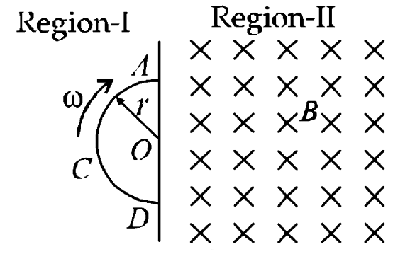
A space is divided by the line AD into two regions. Region I is field free and the region II has a uniform magnetic field B directed into the paper. ACD is a semicircular conducting loop of radius r with centre at O, the plane of the loop being in the plane of the paper. The loop is now made to rotate with a constant angular velocity about an axis passing through O, and perpendicular to the plane of the paper in the clockwise direction. The effective resistance of the loop is R.
Plot a graph between the induced emf and the time of rotation for two periods of rotation.
To solve the problem, we need to find the induced EMF in the semicircular conducting loop as it rotates in a uniform magnetic field. We will then plot a graph of the induced EMF against time for two complete rotations of the loop.
1. Understanding the Setup:
- We have a semicircular conducting loop (ACD) of radius r rotating with a constant angular velocity ω about an axis through point O.
- The loop rotates in a uniform magnetic field B directed into the paper (negative z-direction).
2. Finding the Area of the Loop:
- As the loop rotates, the angle θ covered by the loop at time t is given by:
θ=ωt
- The area A of the semicircular loop that is within the magnetic field at any time t can be expressed as:
A=12r2θ=12r2(ωt)
3. Calculating the Magnetic Flux:
- The magnetic flux Φ through the loop is given by:
Φ=B⋅A=B⋅12r2(ωt)=Bωr2t2
4. Finding the Induced EMF:
- According to Faraday's law of electromagnetic induction, the induced EMF (E) is given by the negative rate of change of magnetic flux:
E=−dΦdt
- Differentiating the expression for flux:
E=−ddt(Bωr2t2)=−Bωr22
- The induced EMF is constant in magnitude and directed according to Lenz's law.
5. Direction of Induced Current:
- When the loop enters the magnetic field, the induced current flows in the anticlockwise direction to oppose the increase in magnetic flux (Lenz's law).
- When the loop exits the magnetic field, the induced current will flow in the clockwise direction to oppose the decrease in magnetic flux.
6. Graph of Induced EMF vs. Time:
- For the first half of the rotation (0 to T/2), the induced EMF is constant and negative (anticlockwise current).
- For the second half of the rotation (T/2 to T), the induced EMF remains constant in magnitude but changes direction (clockwise current).
- This pattern repeats for the second rotation.
Graph Description:
- The graph will show a constant negative value for the first half of the period T/2 and a constant positive value for the second half T/2 to T.
- This pattern will repeat for the second rotation, leading to a square wave-like graph with alternating segments.
- We have a semicircular conducting loop (ACD) of radius r rotating with a constant angular velocity ω about an axis through point O.
- The loop rotates in a uniform magnetic field B directed into the paper (negative z-direction).
- As the loop rotates, the angle θ covered by the loop at time t is given by:
θ=ωt
- The area A of the semicircular loop that is within the magnetic field at any time t can be expressed as:
A=12r2θ=12r2(ωt)
- The magnetic flux Φ through the loop is given by:
Φ=B⋅A=B⋅12r2(ωt)=Bωr2t2
- According to Faraday's law of electromagnetic induction, the induced EMF (E) is given by the negative rate of change of magnetic flux:
E=−dΦdt
- Differentiating the expression for flux:
E=−ddt(Bωr2t2)=−Bωr22
- The induced EMF is constant in magnitude and directed according to Lenz's law.
- When the loop enters the magnetic field, the induced current flows in the anticlockwise direction to oppose the increase in magnetic flux (Lenz's law).
- When the loop exits the magnetic field, the induced current will flow in the clockwise direction to oppose the decrease in magnetic flux.
- For the first half of the rotation (0 to T/2), the induced EMF is constant and negative (anticlockwise current).
- For the second half of the rotation (T/2 to T), the induced EMF remains constant in magnitude but changes direction (clockwise current).
- This pattern repeats for the second rotation.
- The graph will show a constant negative value for the first half of the period T/2 and a constant positive value for the second half T/2 to T.
- This pattern will repeat for the second rotation, leading to a square wave-like graph with alternating segments.
Topper's Solved these Questions
- ELECTROMAGNETIC INDUCTIONBOOK - MOTIONCHAPTER - ELECTROMAGNETIC INDUCTIONEXERCISE - EXERCISE-1
25 Videos
- ELECTROMAGNETIC INDUCTIONBOOK - MOTIONCHAPTER - ELECTROMAGNETIC INDUCTIONEXERCISE - EXERCISE-2 (LEVEL-I)
16 Videos
- ELECTRO MAGNETIC WAVES BOOK - MOTIONCHAPTER - ELECTRO MAGNETIC WAVES EXERCISE - EXERCISE - 3 (SECTION - B)
8 Videos
- ELECTROMAGNETISMBOOK - MOTIONCHAPTER - ELECTROMAGNETISMEXERCISE - Exercise
136 Videos
Similar Questions
A space is divided by the line AD into two regions. Region I is field free and the region II has a uniform magnetic field B directed into the paper. ACD is a semicircular conducting loop of radius r with centre at O, the plane of the loop being in the plane of the paper. The loop is now made to rotate with a constant angular velocity about an axis passing through O, and perpendicular to the plane of the paper in the clockwise direction. The effective resistance of the loop is R.
Obtain an expression for the magnitude of the induced current in the loop.
View SolutionA space is divided by the line AD into two regions. Region I is field free and the region II has a uniform magnetic field B directed into the paper. ACD is a semicircular conducting loop of radius r with centre at O, the plane of the loop being in the plane of the paper. The loop is now made to rotate with a constant angular velocity about an axis passing through O, and perpendicular to the plane of the paper in the clockwise direction. The effective resistance of the loop is R.
Show the direction of the current when the loop is entering into the region II.
View Solution
Knowledge Check
There is a uniform magnetic field directed perpendicular and into the plane of the paper. An irregular shaped conducting loop is slowly changing into a circular loop in the plane of the paper. Then
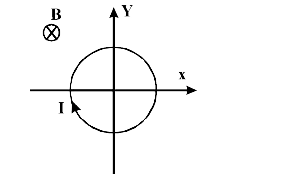
Acurrent is induced in the loop in the anticlockwise directionBcurrent is induced in the loop in the clockwise directionCAltrenating current is induced in the loopDno current is induced in the loopA conducting loop carrying a current I is placed in a uniform magnetic field ponting into the plane of the paper as shown. The loop will have a tendency to
 AcontractBexpandCmove towards +vex−aξsDmove towards −vex−aξs
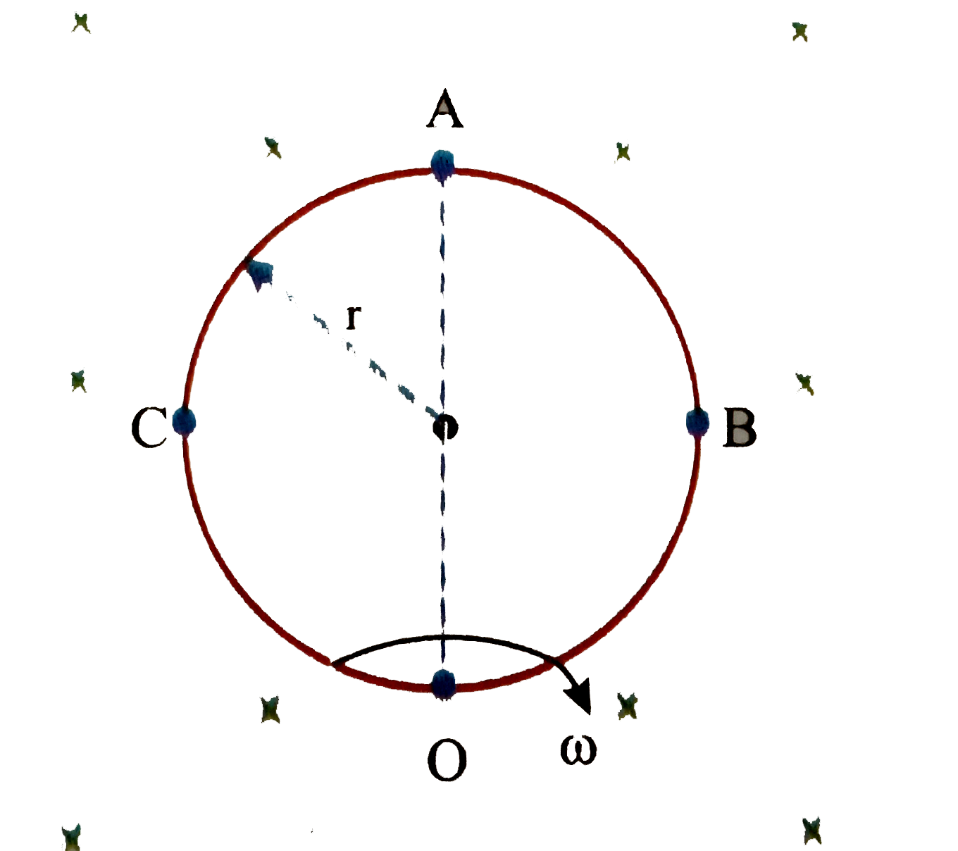
In figure, there is conducting ring having resistance R placed in the plane of paper in a uniform magnetic field B0. If the rings is rotating in the plane of paper about an axis passing through point O and perpendicular to the plane of paper with constant angular speed ω in clockwise direction, then
 Apoint O will be at higher potential than ABthe potential of point B and C will be differentCthe current in the ring will be zeroDthe current in the ring will be 2B0ωr2/R
Space is divided by the line AD into two regions. Region I is field free and the Region II has a unifrom magnetic field B direction into the plane of the paper. ACD is a simicircular conducting loop of radius r with center at O, hte plane of the loop being in the plane of the paper. The loop is now made to rotate with a constant angular velocity ω about an axis passing through O and the perpendicular to the plane of the paper. The effective resistance of the loop is R.

(i) obtain an expression for hte magnitude of the induced cureent in the loop.
(ii) Show the direction of the current when the loop is entering into the Rigion II.
Plot a graph between the induced e.m.f and the time of roation for two periods or rotation.
View SolutionA circular loop of radius a having n turns is kept in a horizontal plane. A uniform magnetic field B exists in a vertical direction as shown in Fig.313. Find the emf induced in the loop if the loop is roated with a uniform angualr velocity ω about
(a) an axis passing through the center and perendicular to the plane of the loop.
(b) the diameter.

View SolutionThere exists a uniform magnetic field ¯¯¯B=B0t¯k in a region. A circular conducting loop of radius r and resistance R is placed with its plane in x-y plane. Determine the current through the loop and sense of the current.
View SolutionA uniform magnetic field B=B0tˆi in a region exists. A circular conducting loop of radius r and resistance R is placed with its plane in yz-plane. Determine the current through the loop and sense of the current.
View SolutionPredict the direction of the induced current in the rectangular loop abcd as it is moved into the region of a uniform magnetic filed →B directed normal to the plane of the loop.

View Solution
