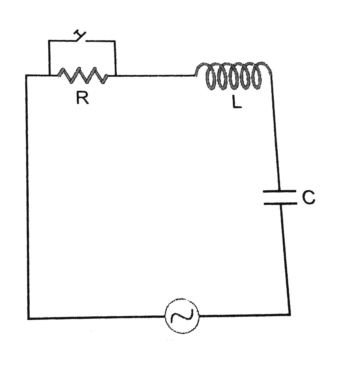
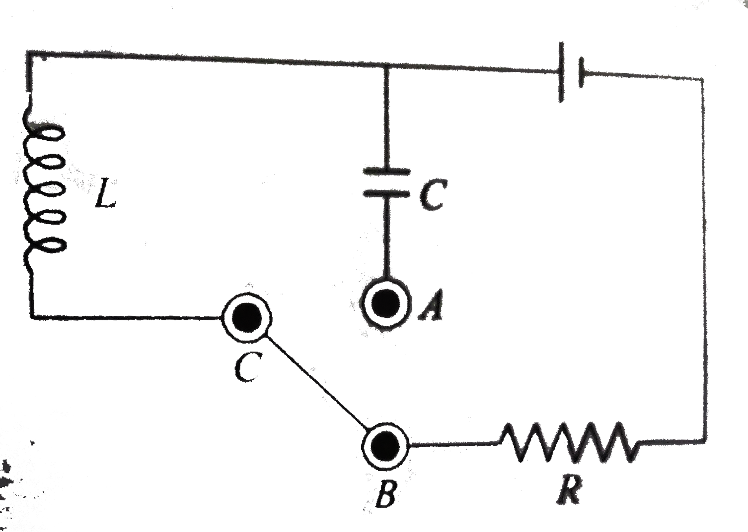
In the LCR circuit shown in Fig., the ac driving voltage is υ=υmsinωt.
(i) Write down the equation of motion for q (t).
(ii) At t=t0, the source stops and R is short circuited.
Now write down how much energy is stored in each of L and C.
(iii) Describe subsequent motion of charges.
The correct Answer is:A
Consider the R-L-C circuit shown in the adjacent diagram.
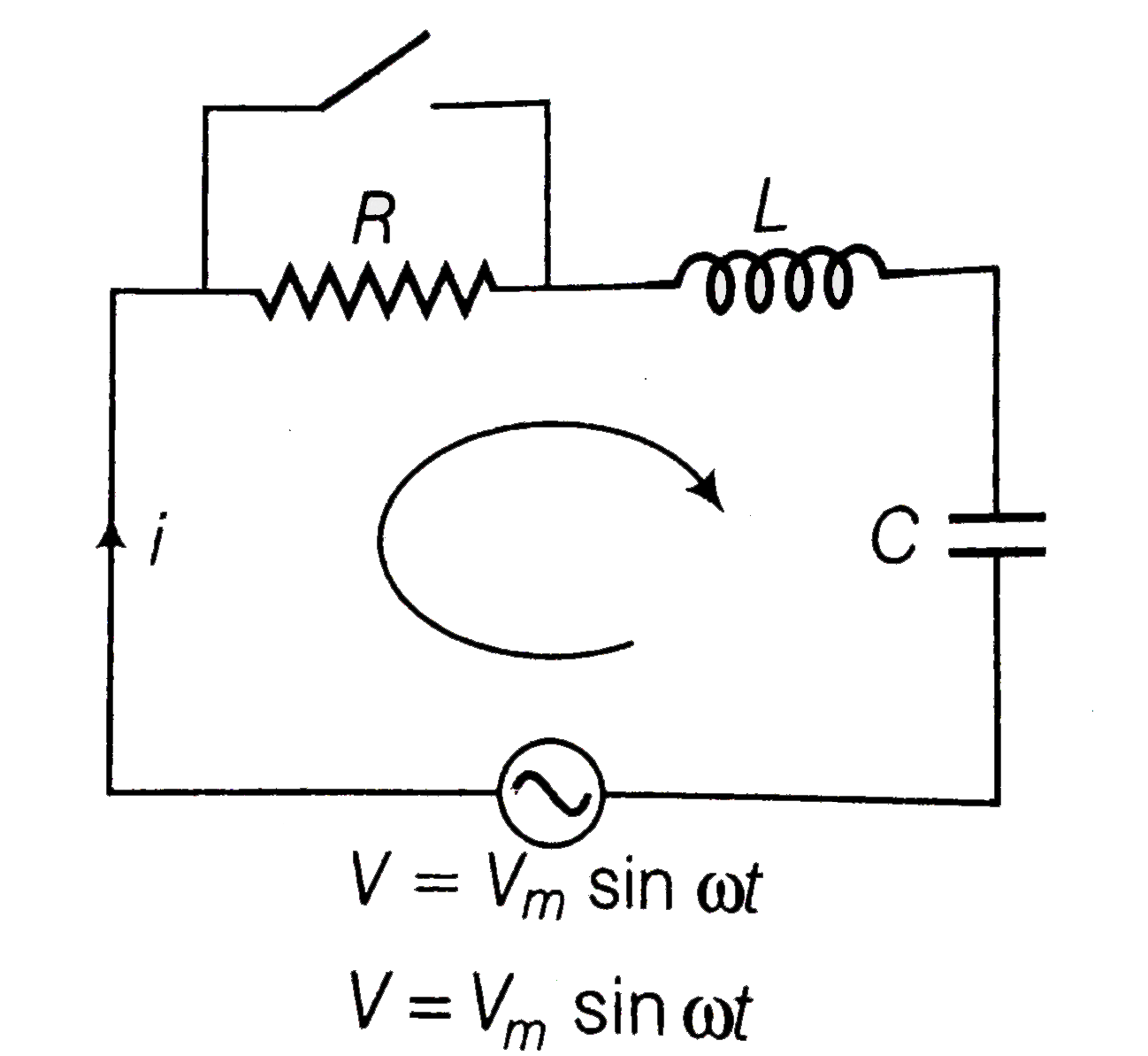
Given,
Let current at any instant be I
Applying KVL in the given circuit
iR+Ldidt+qC−Vmsinωt=0……….(i)
Now, we can write i=dqdt⇒didt=d2q(dt)2
From Eq. (i) dqdtR+Ld2q(dt)2+qC=Vmsinωt
⇒Ld2q(dt)2+Rdqdt+qC=Vmsinωt
This is the required equation of variation (motion) of charge.
b) Let q=qmsin(ωt+ϕ)=−qmcos(ωt+ϕ)
i=imsin(ωt+ϕ)=qmωsin(ωt+ϕ)
im=VmZ=Vm√R2+(XC−XL)2
ϕ=tan−1(Xc−XL)R
Where R is short circuited at t=t0, energy is stored in L and C.
UL=12Li2=12LVm√R2+(XC−XL)2sin2(ωt0+ϕ)
and UC=12×q2C=12C[q2mcos2(ωt0+ϕ)]
=12C⎡⎢
⎢
⎢⎣Vm√R2+(XC−XL)22⎤⎥
⎥
⎥⎦
=12C×(imω)2cos2(ωt0+ϕ)
=i2m2Cω2cos2(ωt0+ϕ) (∴im=qmω]
=12C⎡⎢
⎢
⎢⎣Vm√R2+(XC−XL)22⎤⎥
⎥
⎥⎦(cos2(ωt0+ϕ)
c) When R is a short circuited, the circuit becomes an L-C oscillaor. The capacitor will go on discharging and all energy will go to L and back and forth. Hence, there is oscillation of energy from electrostatic to magnetic and magnetic to electrostatic.
Topper's Solved these Questions
Similar Questions
For an LCR circuit driven at frequency ω, the equation reads Ldidt+Ri+qC=υi=υmsinωt
(i) Multiply the equation by I and simplify where possible. (ii) Interpret each term physically.
(iii) Cast the equation in the form of a conservation of energy statement.
(iv) Intergrate the equation over one cycle to find that the phase difference between υ and i must be acute.
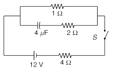
View SolutionIn the circuit shown in the figure, switch S is closed at time t=0. Charge on positive plate of capacitor is q at time t.
(a) Derive a differential equation for q at time t.
(b) Solve the equation to write q as a function of time.
(c) Put t = 0 and t=∞ in your equation to get charge on the capacitor at these times.
View Solution
Knowledge Check
A series LR circuit is connected to a voltage source with V(t) = V0 sin ω t. after very large time, current I(t) behaves as (t0>>LR)
A B
B C
C D
D
In an a.c. Circuit the voltage applied is E=E0sin(ω)t. The resulting current in the circuit is I=I0sin((ω)t−(π2)). The power consumption in the circuit is given by
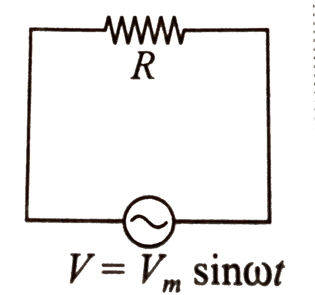
AP=√2E0I0BP=E0I0√2CP=zeroDP=E0I02An ac source of voltage V=Vmsinωt is connected across the resistance R as shown in figure. The phase relation between current and voltage for this circuit is
 Aboth are in phaseBboth are out of phase by 90∘Cboth are out of phase by 120∘Dboth are out of phase by 180∘
In the circuit shows in Fig the capacitor is initially uncharged and the two - way switch is connected in the position BC. Find the current through the resistence R as a function of time t. After time t=4 ms, the switch is connected in the position AC. Find the frequency of oscillation of the capacitor of the circuit in the position, and the maximum charge on the capacitor C. At what time will the energy stored in the capacitor be one-half of the total energy stored in the circuit? It is given L=2×10⁻⁴H,C=5mF,R=In210Ω and emf of the battery =1V.
View SolutionIn a circuit shown in fig. the capacitance of each capacitor is equal to C and the resistance, to R One of the capacitor was connected to a voltage V0 and then at the moment t=0 was shorted by means of the swich Sw. Find:
(a) a current I in the circuit as a function of time t:
(b) the amount of generated heat provided a dependence I(t) is known.

View SolutionIn a series LCR circuit connected to an a.c. source of variable frequency and voltage V=Vmsinωt draw a plot showing the variation of current (I) with angular frequency (w) for two different values of resistance R1 and R2(R1>R2). Write the condition under which the phenomenon of resonance occurs. For which value of the resistance out of the two curves, a sharper resonance is produced ? Define Q-factor of the circuit and give its significance.
View SolutionA source of a.c. voltage V=Vmsinωt is connected to a series combination of a capacitor C and a resistor R. Draw the phasor diagram and use it to obtain the expression for (i) impedance of the circuit, and (ii) phase angle.
View SolutionIn a circuit shown in fig. the capacitance of each capacitor is equal to C and the resistance, to R One of the capacitor was connected to a voltage V0 and then at the moment t=0 was shorted by means of the swich Sw. Find:
(a) a current I in the circuit as a function of time t:
(b) the amount of generated heat provided a dependence I(t) is known.

View Solution
