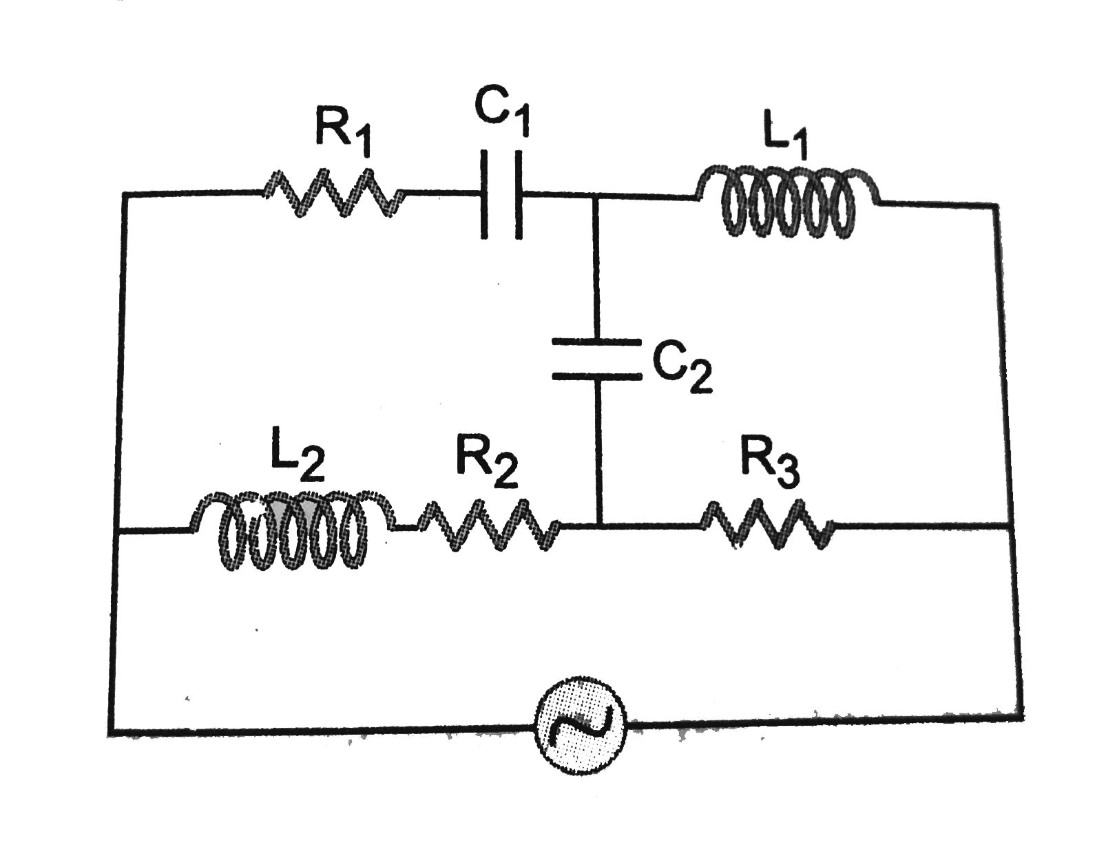
Draw the effective equivalent circuit of the circuit show in Fig. at very high frequencies and find the effective impedance.
Video Solution
Text Solution
The correct Answer is:A
We know that inductive reactance XL=2πfL
and capacitance reactance XC=12πfC
For very high frequencies (f→∞),XL→∞ and XC→0
When reactance of a circuit is infinite it will be considered as open circuit. When reactance of a circuit is zero it will be considered as short circuited.
So, C1,C2→ shorted and L1,L2→ opened.
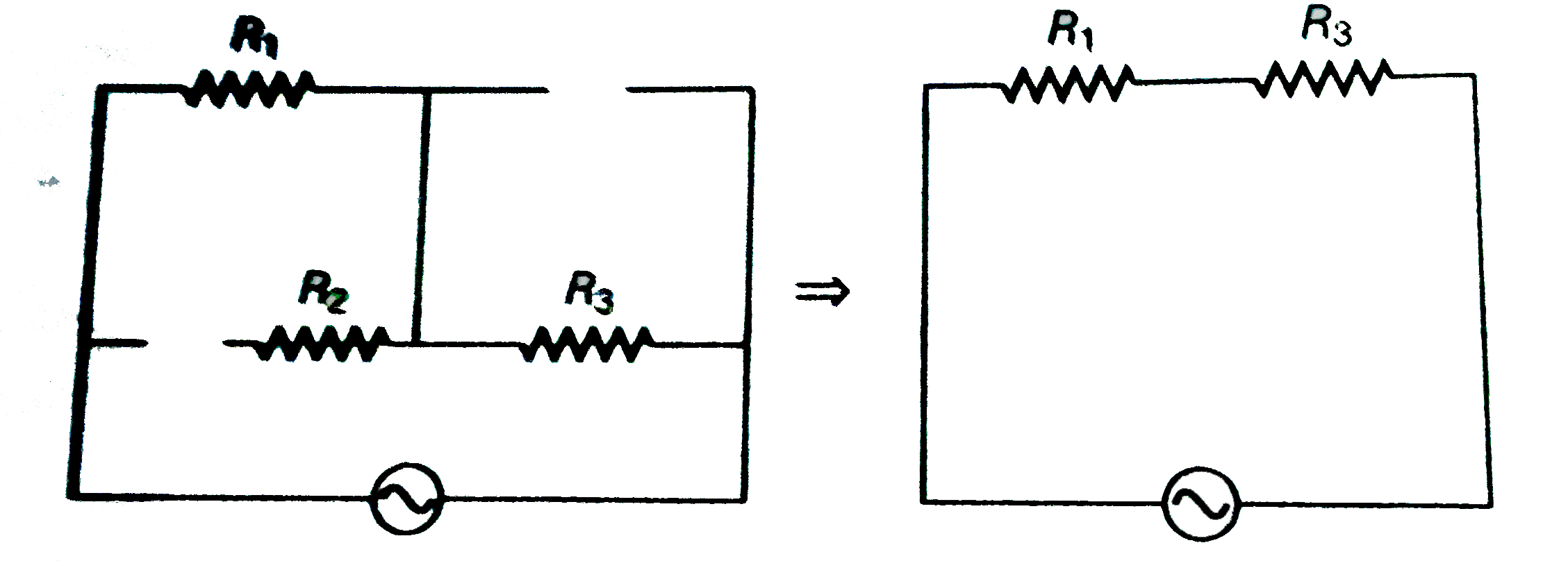
So, effective impedance =Req=R1+R3
|
Topper's Solved these Questions
Similar Questions
Knowledge Check
The natural frequency of the circuit shows in Fig. is
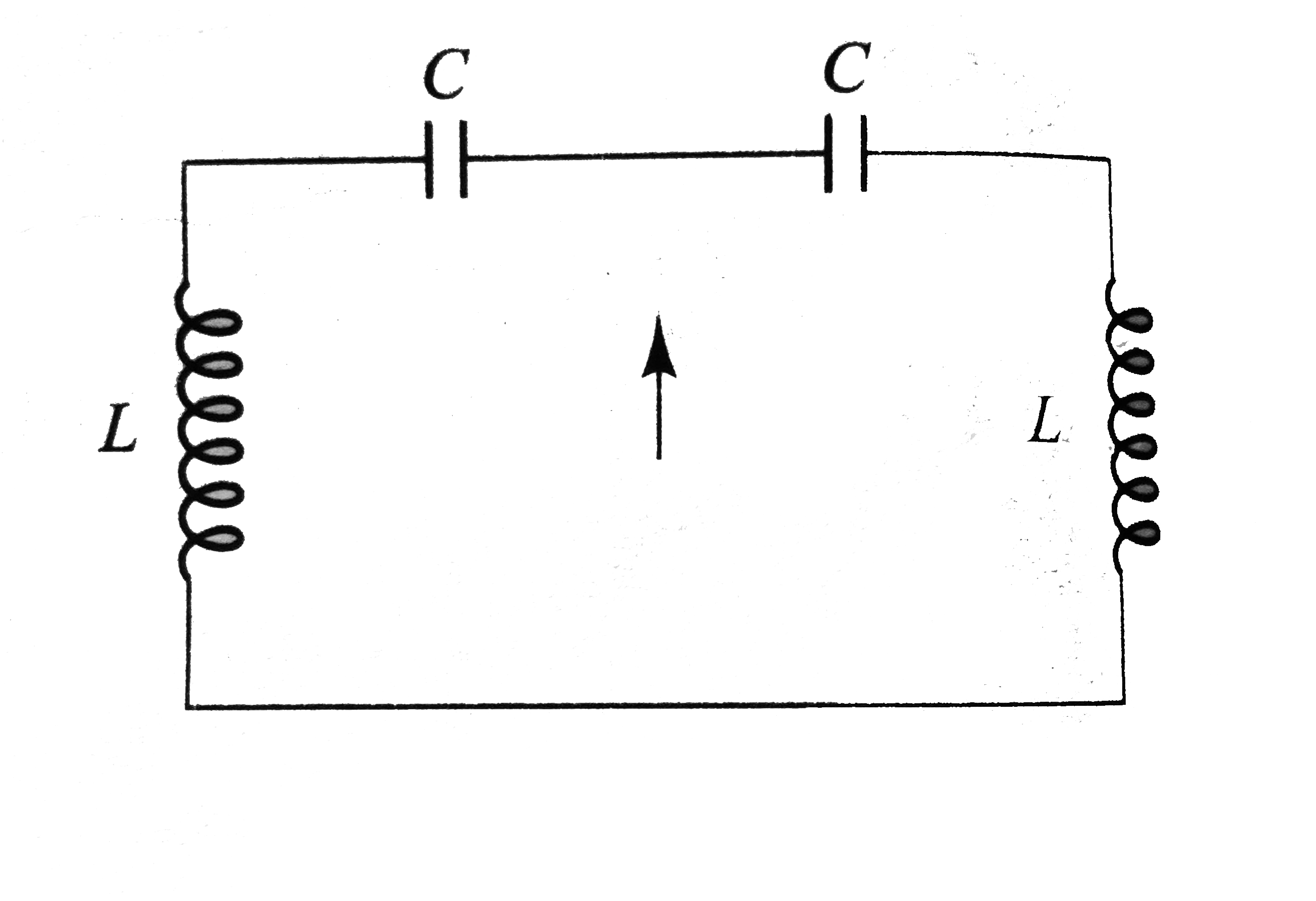 A1√LCB1√2LCC2√LCDNone of these
In the circuit shown in fig, the resonant frequency is
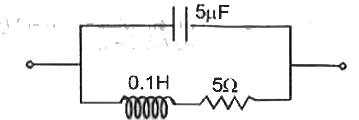 A75kcsB750kcsC7.5kcsD75mcs
Resultant impedence of the circuit is
A3.5ωB4.0ΩC4.5ΩD5.0Ω
Find the equivalent resistnace of the circuit shown in fig between the points A and B

View SolutionFind the effective resistance of the following circuit :
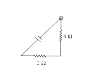
View SolutionWhat is the effective resistance in the given circuit?
View Solution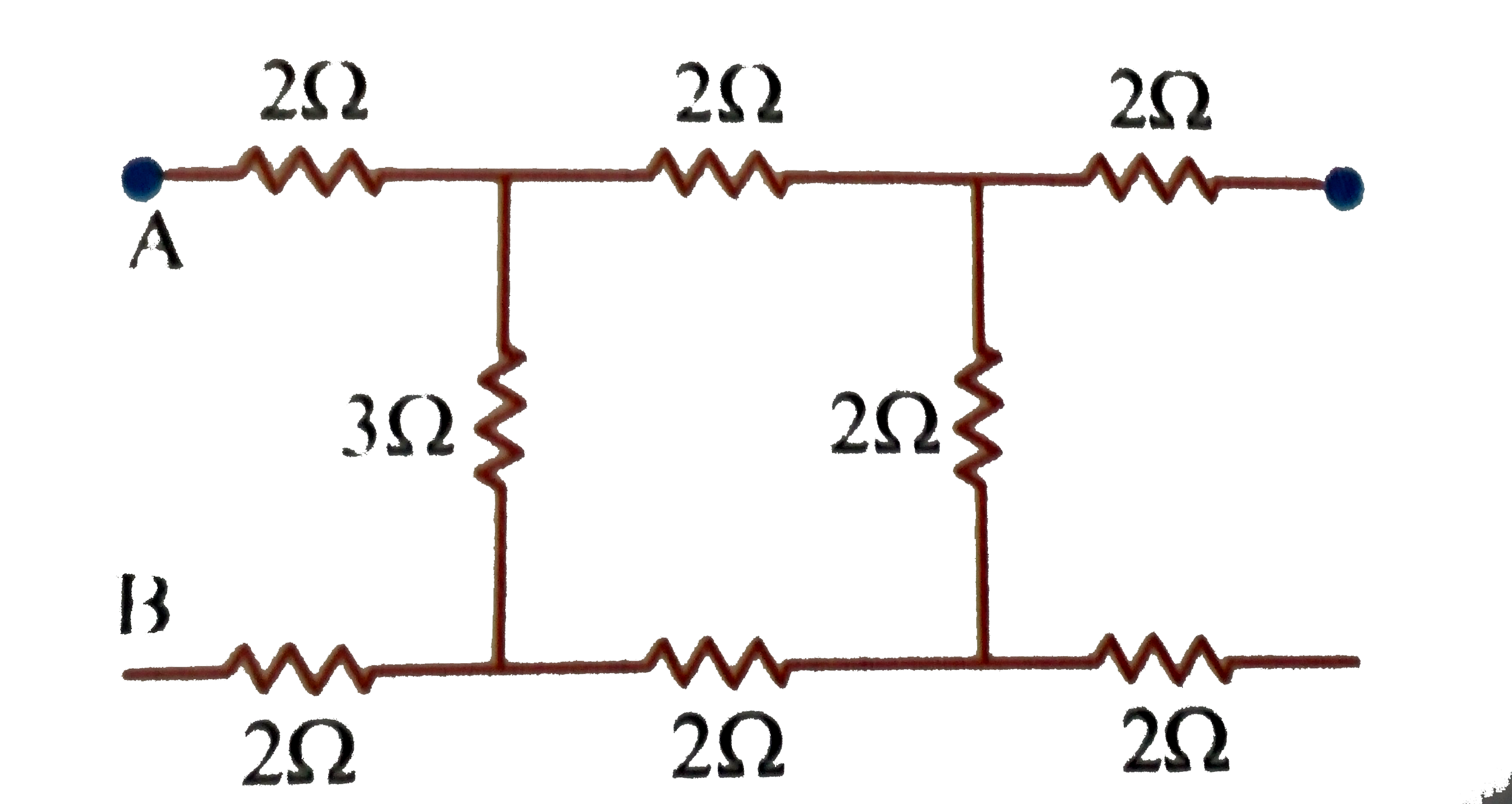
The effective between A&B in the given circuit is
View SolutionIn the circuit shows in Fig the switch is closed at t=0.

View Solution


