In the circuit shown, the internal resistances of the batteries are indicated next to them. Choose the correct option(s):
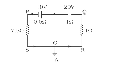
(A) The potential at P is -7.5
The potential at Q is -1V
The potential at R is zero
The potential at S is zero
The current in the circuit I=(20−10)(7.5+0.5+1+1)=1010−1amp
The potential difference across PS, Vps=7.5×1=7.5V
The potential difference across Q,R, VQR=1×1=1V
As point G is connected to earth, hence potentials of R and S are zero.
The direction of the current in the circuit is from P to S, hence point P is at higher potential
∴Vp=7.5V
Similarly, VQ=−V∴ Hence (B) ( C) and (D) are correct
Similar Questions
In the given circuit if the internal resistance of the batteries are negligible, then for what value of resistance R(inΩ) will the thermal power generated in it be maximum.

View SolutionShown n batteries connected to form a circuit. The resistances denote the internal resistances of the batteries which are related to the emf's as ri=k(ε)iwhere K is a constant. The solid dots represent the terminals of the batteries. Find (a)the current through the circuit and (b) the potential difference between the terminals of the ith battery.

View Solution
Knowledge Check
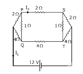
For the resistance network shown in the figure, choose the correct options (s)
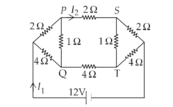 AThe current through PQ is zero.BI1=3ACThe potential at S is less than that at Q.DI2=2A
A capacitor of 4μF is connected as shown in the circuit. The internal resistance of the battery is 0.5Ω. The amount of charge on the capacitor plates will be
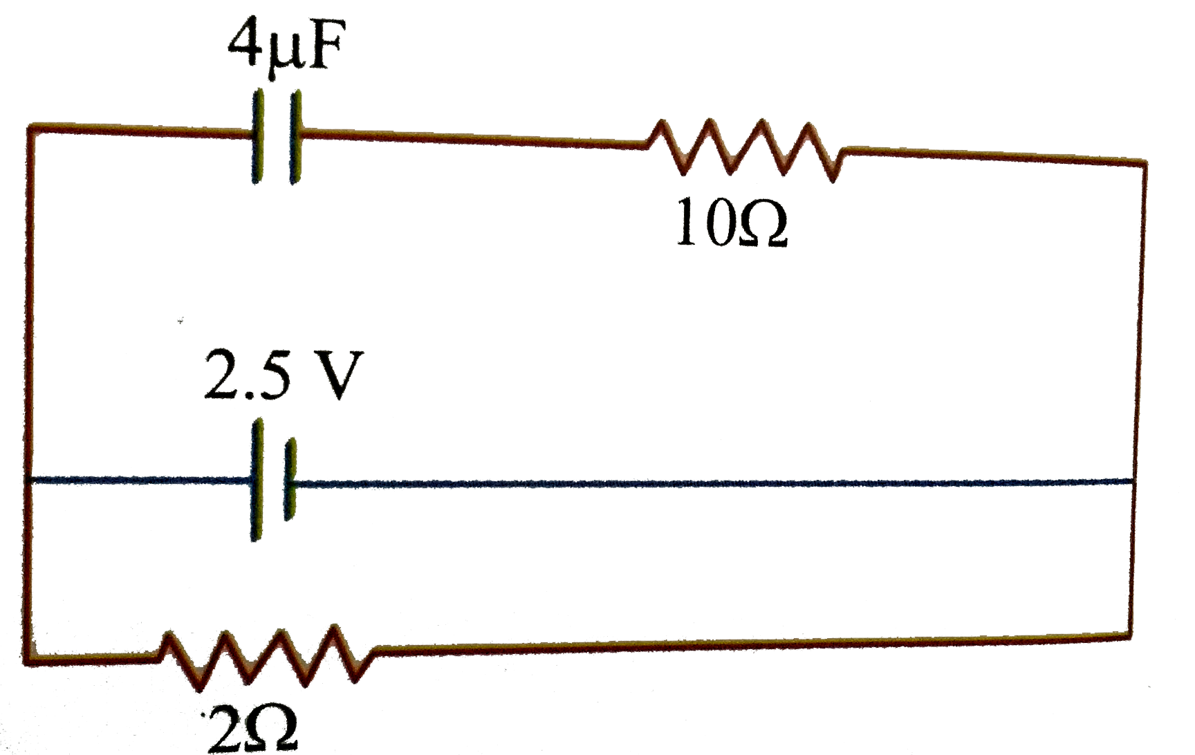 .A0B4μCC16μCD8μC
Consider the situation as shown in the figure. Choose the correct option.
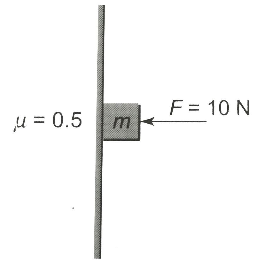 AThe friction force on the block is 1Nifm=0.1kgBThe friction on the block is 5Nifm=1.0kgCBoth (1) and (2) are correctDBoth (1) and (2) are incorrect
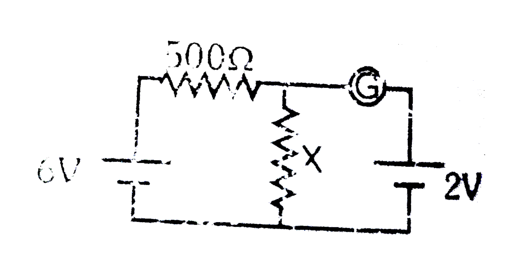
The reading of a galvanometer connected in the circuit is zero. If the internal resistance of a battery is zero then find the value of X.
View SolutionFor the resistance network shown in the figure , choose the correct options (s ).
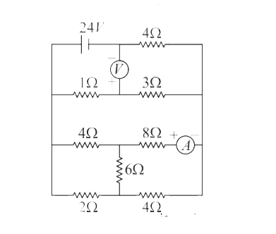
View SolutionIn the circuit shown, the battery, the ammeter and the voltmeter are ideal. Pick the correct choice(s) :
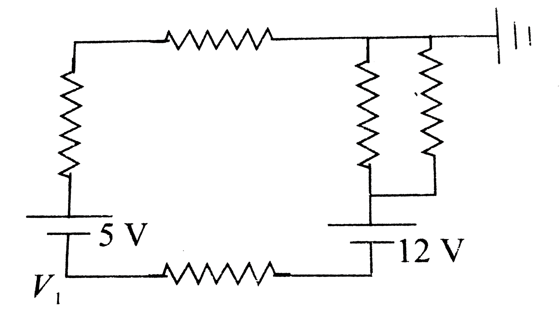
View SolutionIn the circuit shown, each resistance is 2Ω. The potential V1 is an indicated in the circuit. What is the magnitude of V1 in volt ?
View SolutionThere is a circuit diagram in which capacitors, resistors & battery are given. Then choose the correct option (s) (Assume initially all the capacitors are unchanrged)
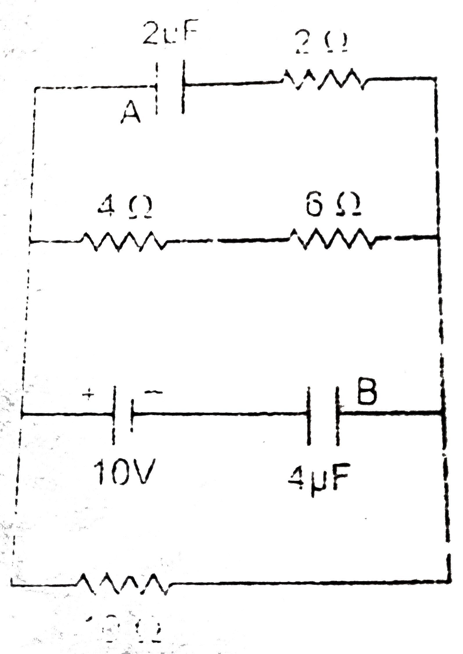
View Solution
