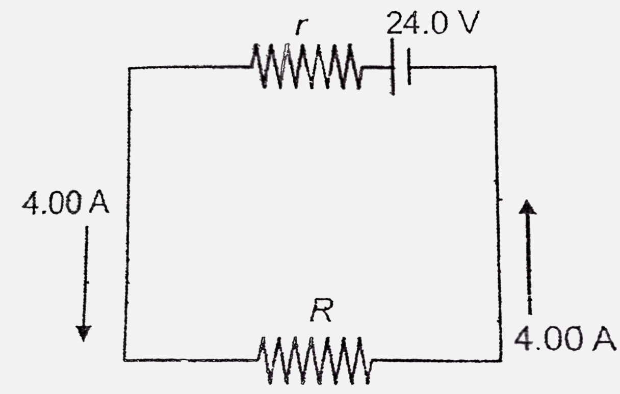
Consider the circuit shown in Figure . The terminal voltage of the 24.0 V battery is 21.2V. What are
(a) The internal resistance r of the battery and
(b) The resistance R of the circuit resistor ?
(a) 0.7Ω,(b)5.3Ω
Topper's Solved these Questions
- CURRENT ELECTRICITYBOOK - AAKASH INSTITUTECHAPTER - CURRENT ELECTRICITYEXERCISE - ASSIGNMENT(SECTION-A(OBJECTIVE TYPE QUESTIONS))
59 Videos
- CURRENT ELECTRICITYBOOK - AAKASH INSTITUTECHAPTER - CURRENT ELECTRICITYEXERCISE - ASSIGNMENT SECTION-B(OBJECTIVE TYPE QUESTION ))
31 Videos
- CURRENT ELECTRICITYBOOK - AAKASH INSTITUTECHAPTER - CURRENT ELECTRICITYEXERCISE - ASSIGNMENT SECTION-J
10 Videos
- COMMUNICATION SYSTEMS BOOK - AAKASH INSTITUTECHAPTER - COMMUNICATION SYSTEMS EXERCISE - ASSIGNMENT SECTION D (Assertion-Reason)
10 Videos
- DUAL NATURE OF RADIATION AND MATTER BOOK - AAKASH INSTITUTECHAPTER - DUAL NATURE OF RADIATION AND MATTER EXERCISE - ASSIGNMENT (SECTION-D)
10 Videos
Similar Questions
In the circuit shown in Fig. 4.63, the terminal voltage of the battery is 6.0 V. Find the current I through the 18Ω resistor.
View Solution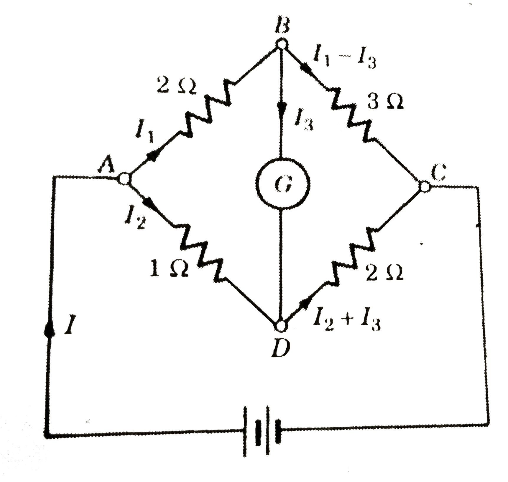
In the circuit shown in figure. Find the currents I,I1,I2andI3 given that emf of th battery=2V, internal resistance of the battery =2Ω and resistance of the galvanomter =4Ω.
View Solution
Knowledge Check
Consider the circuit shown in the figure. Taking the potential to be zero at the negative terminal of the battery :
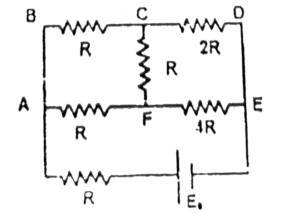 APotential at F will be higher than the potential at CBCurrent in AF will be greater than that in BCCDirection of current in CF will be from C to FDCurrent in FE will be greater than current in CD
Consider a simple circuit shown in Fig. 2(ET).2. stands for a variable resistance R'.R' can vary from R0 to infinity. r is internal resistance of the battery (r<<R<<lR0)
 APotential drop across AB is nearly constant as R' is variedBCurrent through R' is nearly a constant as R' is variedCCurrent I depends sensitively on R'DI≥Vr+R always
A battery of emf 2 V and initial resistance 1Ω is
connected across terminals A and B of the circuit shown
in figure
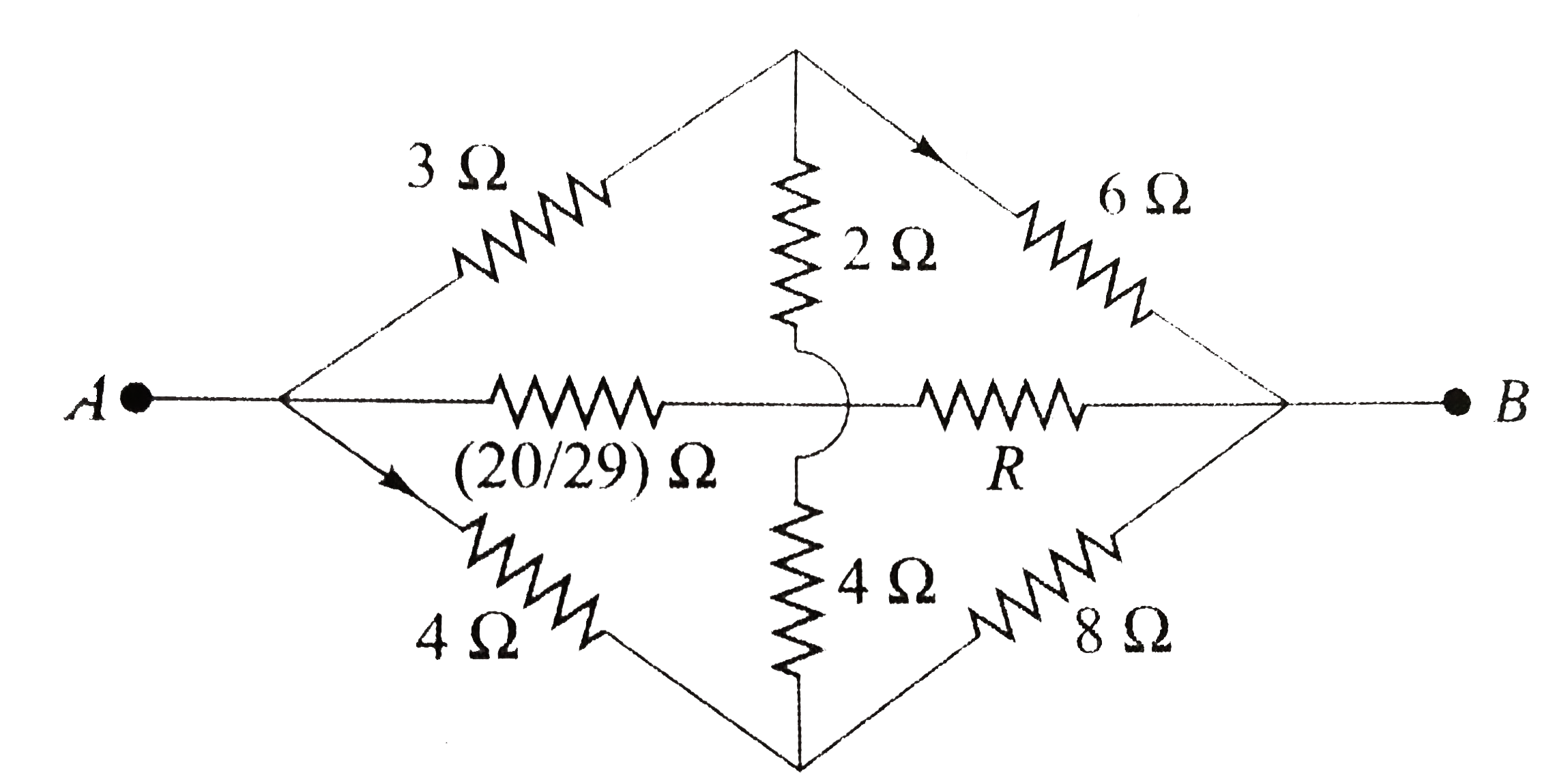 . AThermal power generated in the external circuit will be maximum possible when R=16/25Ω.BMaximum possible thermal power generated in the external circuit is equal to 4 W.CRatio of current through 3Ω to that through 8Ω is independent of R.DNone of above.
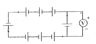
in the circuit shown in the figure, each battery is of 5 V and has an internal resistance of 0.2 Omega What is the reading of the ideal voltmeter V
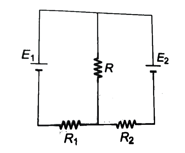
View SolutionIn the circuit shown in figure, the emfs of batteries are E1, and E2 which have internal resistances R1, and R2. At what value of the resistance R will the thermal power generated in it be the highest? What it is?
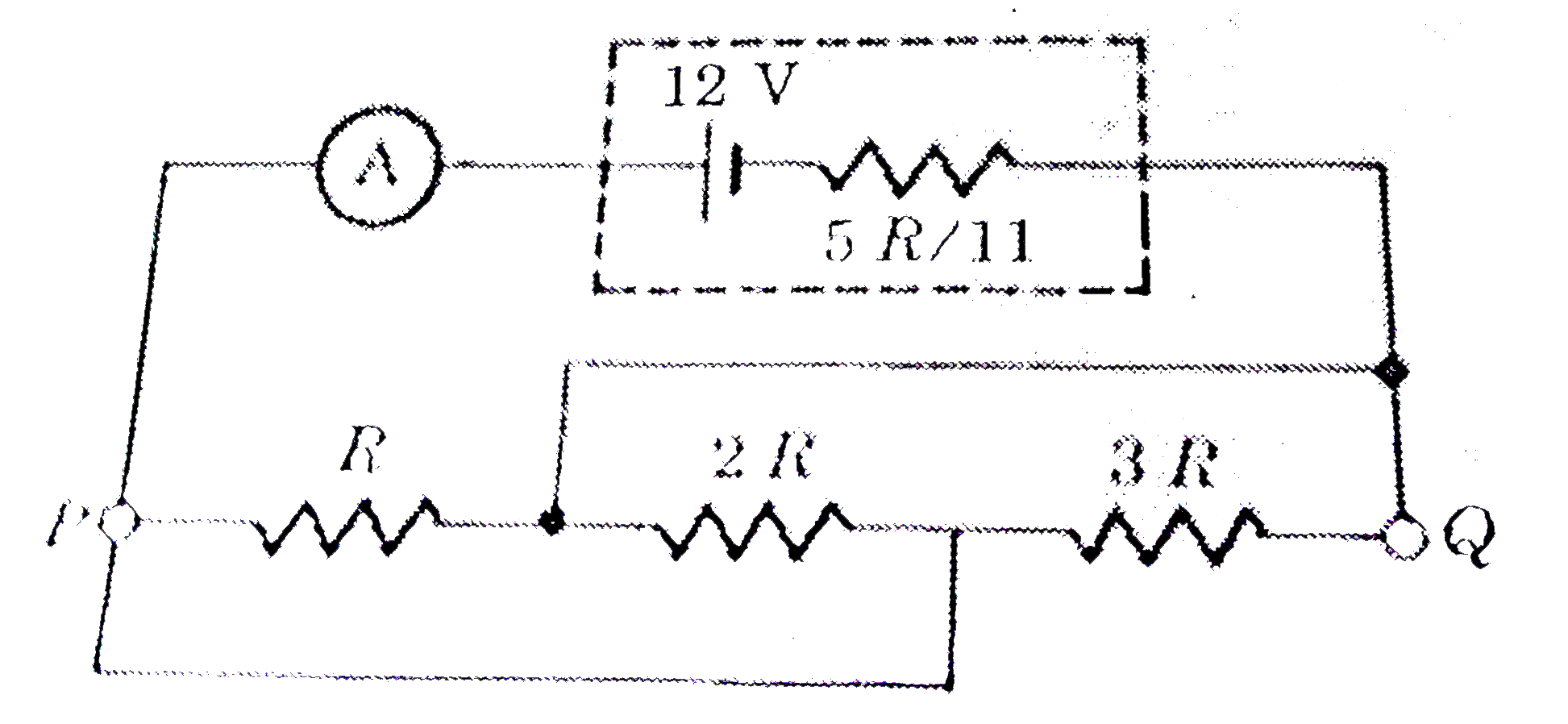
View SolutionIn the circuit shown in Fig. 4.64, the battery has an emf of 12.0 V and an internal resistance of 5R/11. If the ammeter reads 2.0 A, what is the value of R ?
View SolutionIn the circuit shows in Fig. 6.42, resistors X and Y, each with resistance R, are connected to a 6V battery of negligible internal resistance. A voltmetre, also of resistance R, is connected across Y.
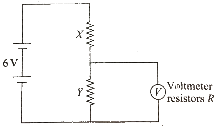
What is the reading of the voltmeter?
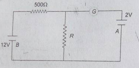
View SolutionIn the circuit, the galvanometer G shows zero deflection. If the batteries A and B have negligible internal resistance, the value of the resistor R will be
View Solution
