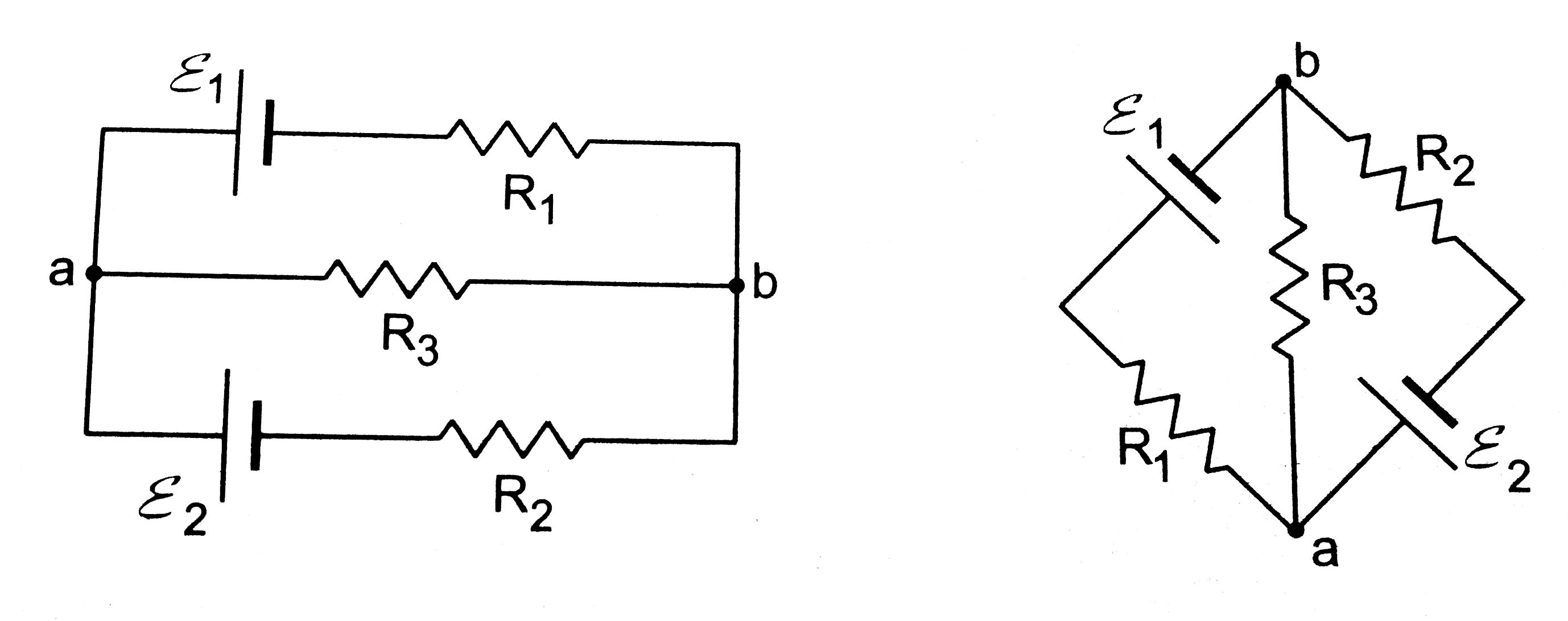
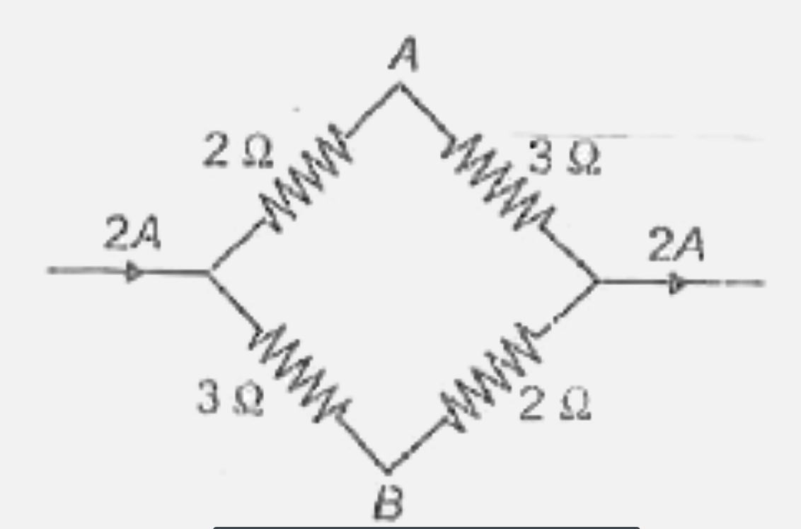
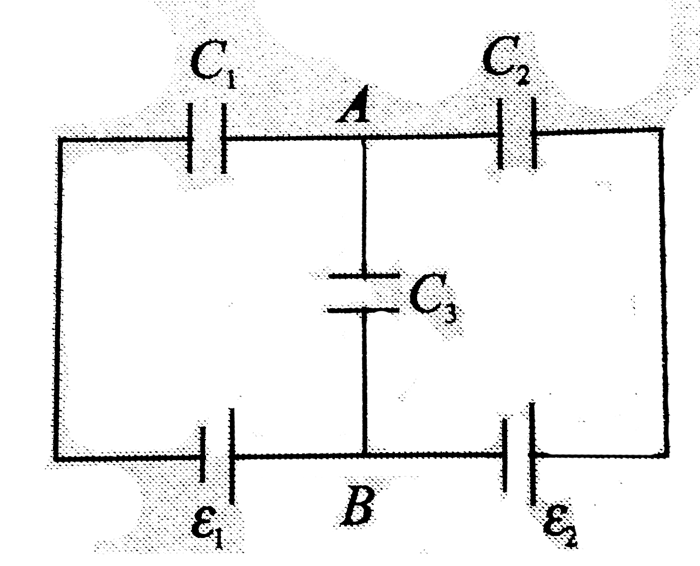
Find the potential difference for the circuit shown in the figure .
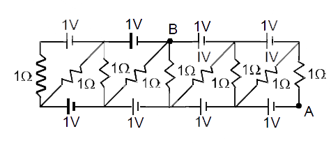
Video Solution
Text Solution
volt
|
Topper's Solved these Questions
- CURRENT ELECTRICITYBook:MOTIONChapter:CURRENT ELECTRICITYExercise:EXERCISE -3 (Level -II) SECTION E- Electrical Power & Energy
Explore 3 Videos
- CURRENT ELECTRICITYBook:MOTIONChapter:CURRENT ELECTRICITYExercise:EXERCISE -3 (Level -II) SECTION F- Electrical Instrument + Exp. Verifying ohm s law & Specific Resistance Using Meter Brige & post Office + Potentiometer (EMF & Int Res.)
Explore 3 Videos
- CURRENT ELECTRICITYBook:MOTIONChapter:CURRENT ELECTRICITYExercise:EXERCISE -3 (Level -II) SECTION B- Resistance & resistivity ,Ohms law +VI (Volt - Curr.) Characteristics + Colour Code + Temp . Dependence
Explore 6 Videos
- CONSTRAINED MOTION Book:MOTIONChapter:CONSTRAINED MOTION Exercise:EXAMPLES
Explore 12 Videos
- ELASTICITYBook:MOTIONChapter:ELASTICITYExercise:EXERCISE -3
Explore 60 Videos
Similar Questions
Knowledge Check
Find VP−VQ in the circuit shown in figure.
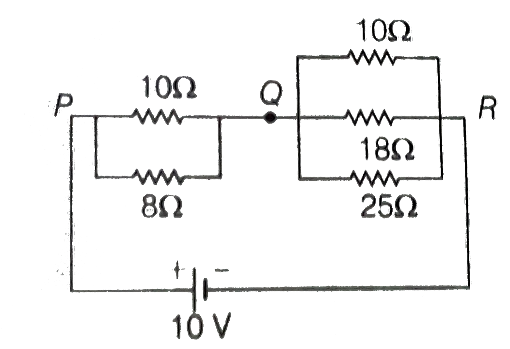 A6.68 VB8 VC4.65 VD7 V
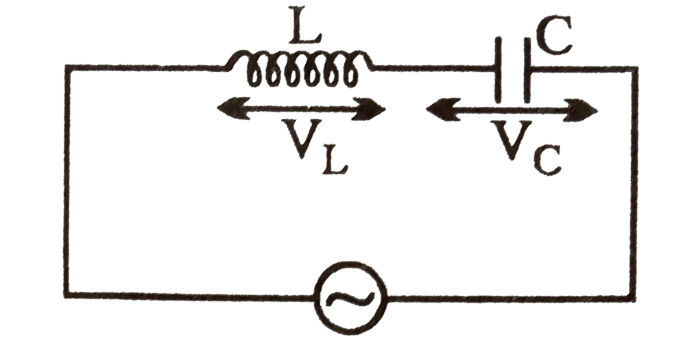
The current I, potential difference VL across the inductor and potential difference VC across the capacitor in circuit as shown in the figure are best represented vectorially as
 A
A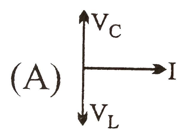 B
B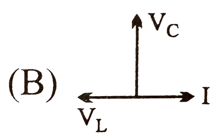 C
C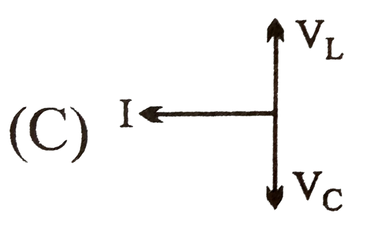 D
D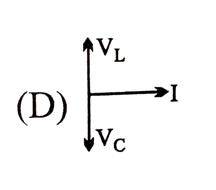
The potential difference between A and B in the circuit shown is -
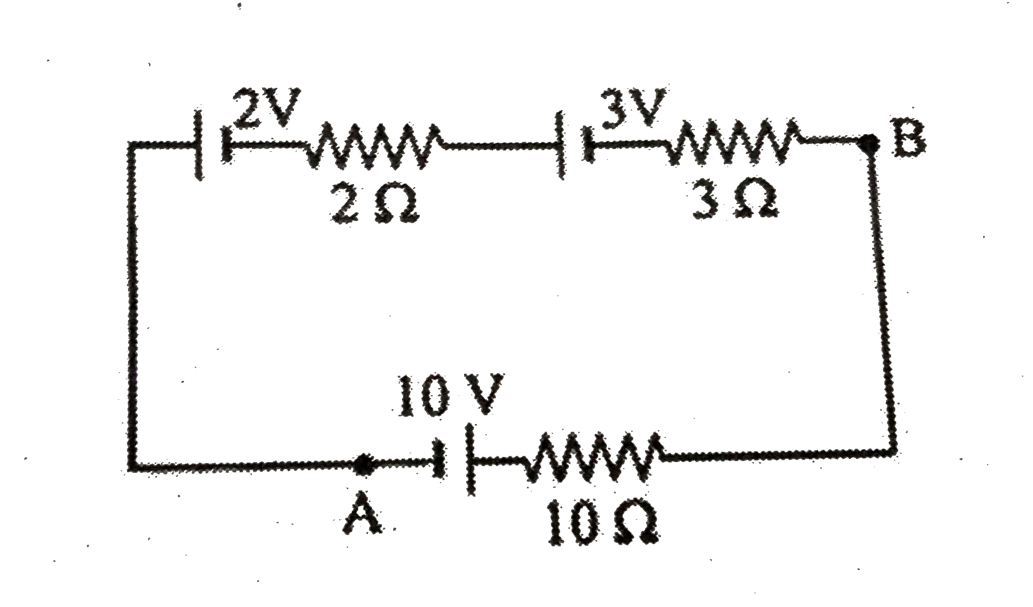 A10VB5 VC15 VDzero
Potential difference VB−VA in the network shown is
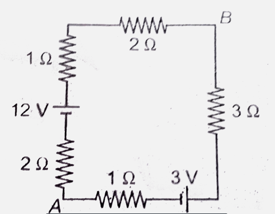
View SolutionThe potential difference VA−VB for the circuit shown in fig. is. −(22/x)V. find the value of x.
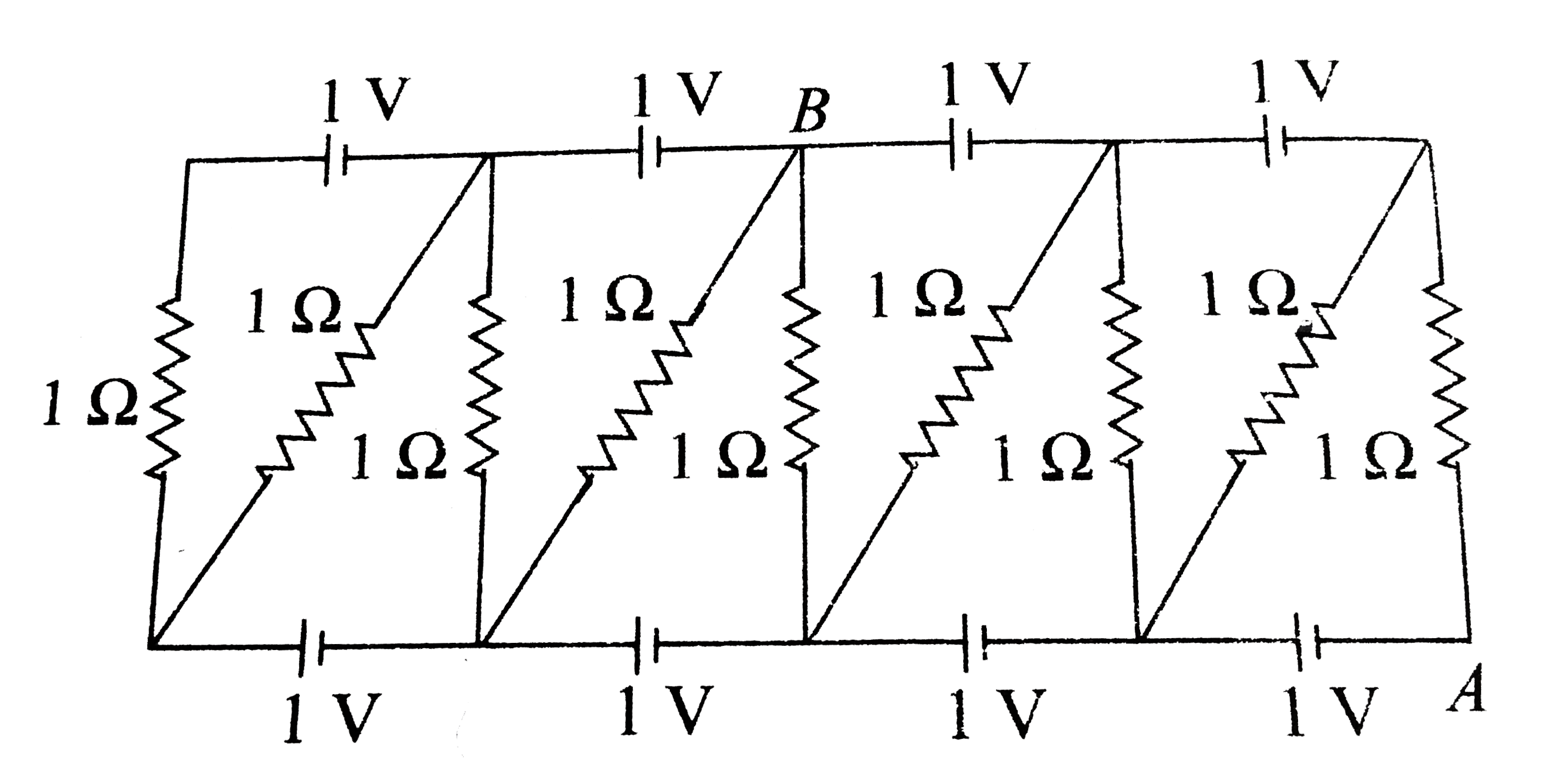
View SolutionPotential difference across AB in the circuit as shown in figure.

View SolutionFind the potential difference VA−VB between points A and B of the circuit shown in.
 .
.
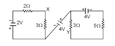
View SolutionDetermine the potential difference between X and Y in the circuit shown in figure.
View Solution

