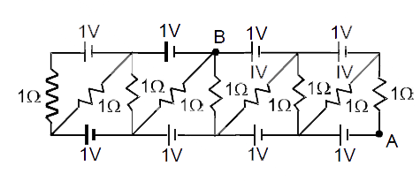
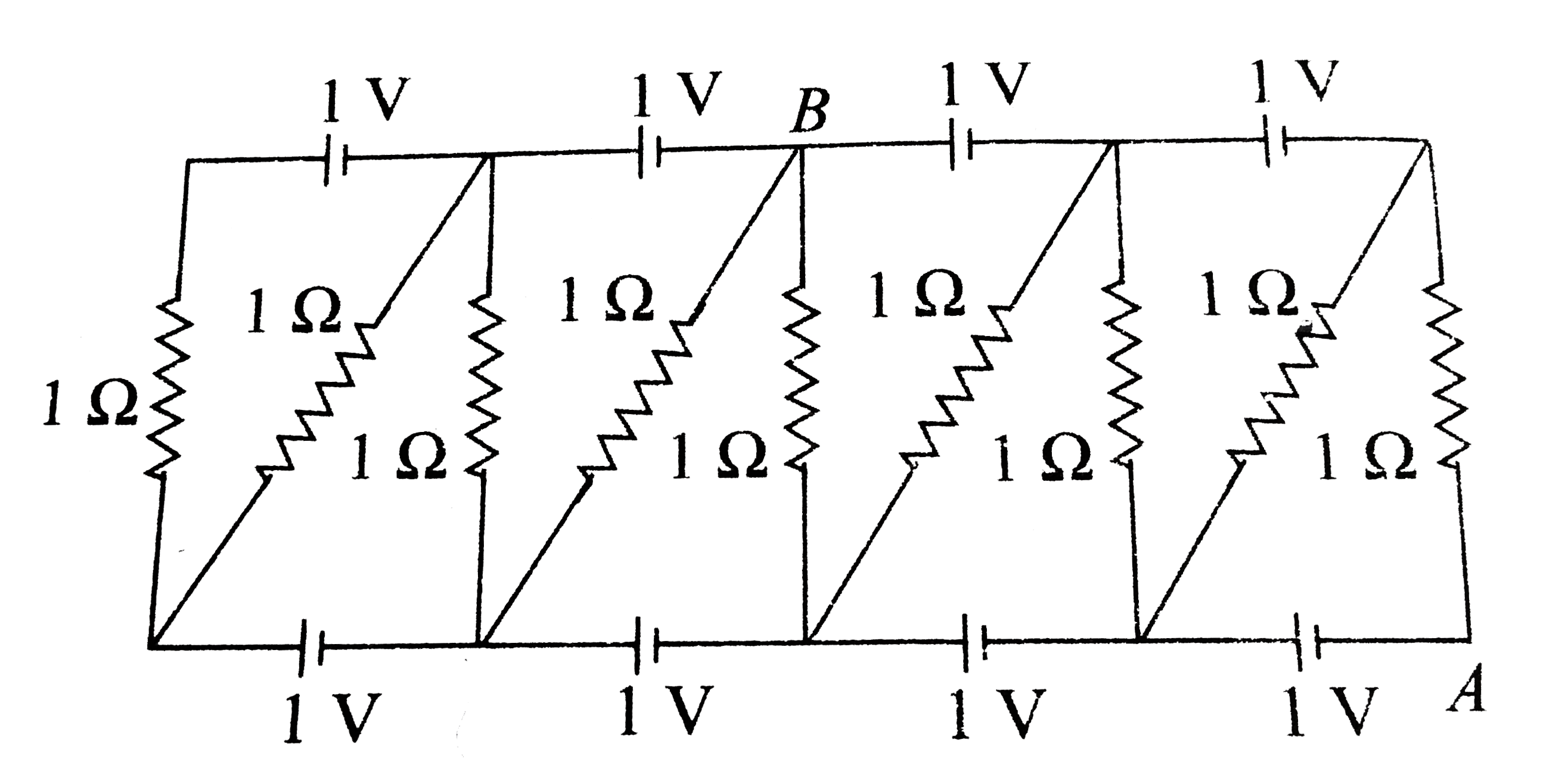
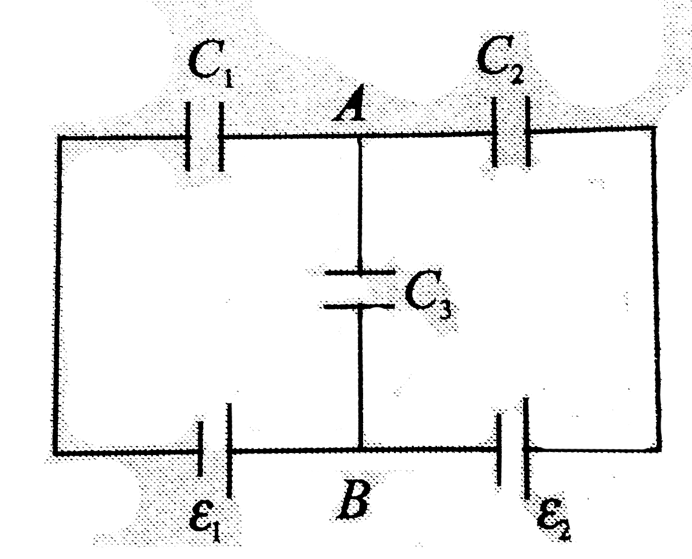
The potential difference VA−VB for the circuit shown in fig. is. −(22/x)V. find the value of x.
Video Solution
Text Solution
The correct Answer is:9
At junction C: i1+i2=I,
where i1=0−x1,i2=1−x1
At D: 4i+i1=0 solve to get x=49
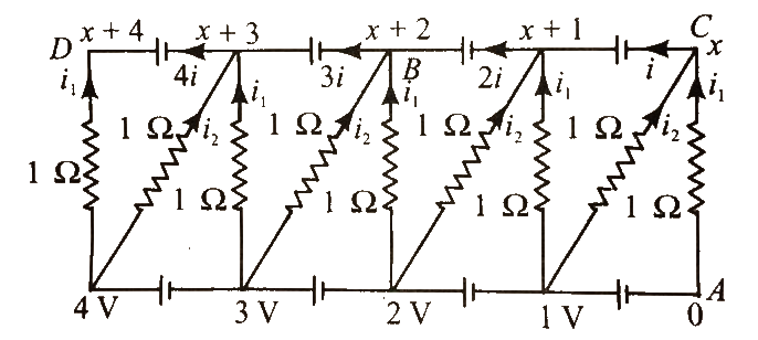
Now VA−i1+1=VBorVAorVB=−(2+49)=−229V
|
Topper's Solved these Questions
- ELECTRIC CURRENT AND CIRCUITBOOK - CENGAGE PHYSICSCHAPTER - ELECTRIC CURRENT AND CIRCUITEXERCISE - Comprehension
35 Videos
- ELECTRIC CURRENT & CIRCUITSBOOK - CENGAGE PHYSICSCHAPTER - ELECTRIC CURRENT & CIRCUITSEXERCISE - Kirchhoff s law and simple circuits
15 Videos
- ELECTRIC FLUX AND GAUSS LAWBOOK - CENGAGE PHYSICSCHAPTER - ELECTRIC FLUX AND GAUSS LAWEXERCISE - MCQ s
38 Videos
Similar Questions
Knowledge Check
Find VP−VQ in the circuit shown in figure.
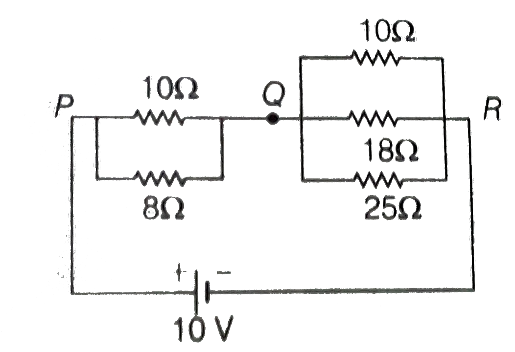 A6.68 VB8 VC4.65 VD7 V
The potential difference between points A and B in the circuit shown in fig. 5.317 is 16V. Then
 Athe current through the 2Ω resistance is 3.5ABthe current through 4Ω resistance is 2.5ACthe current through 3Ω resistance is 1.5ADthe potential difference between the terminals of the 9V battery is 7V
The potential difference (VA−VB) between the point A and B as shown in the figure is
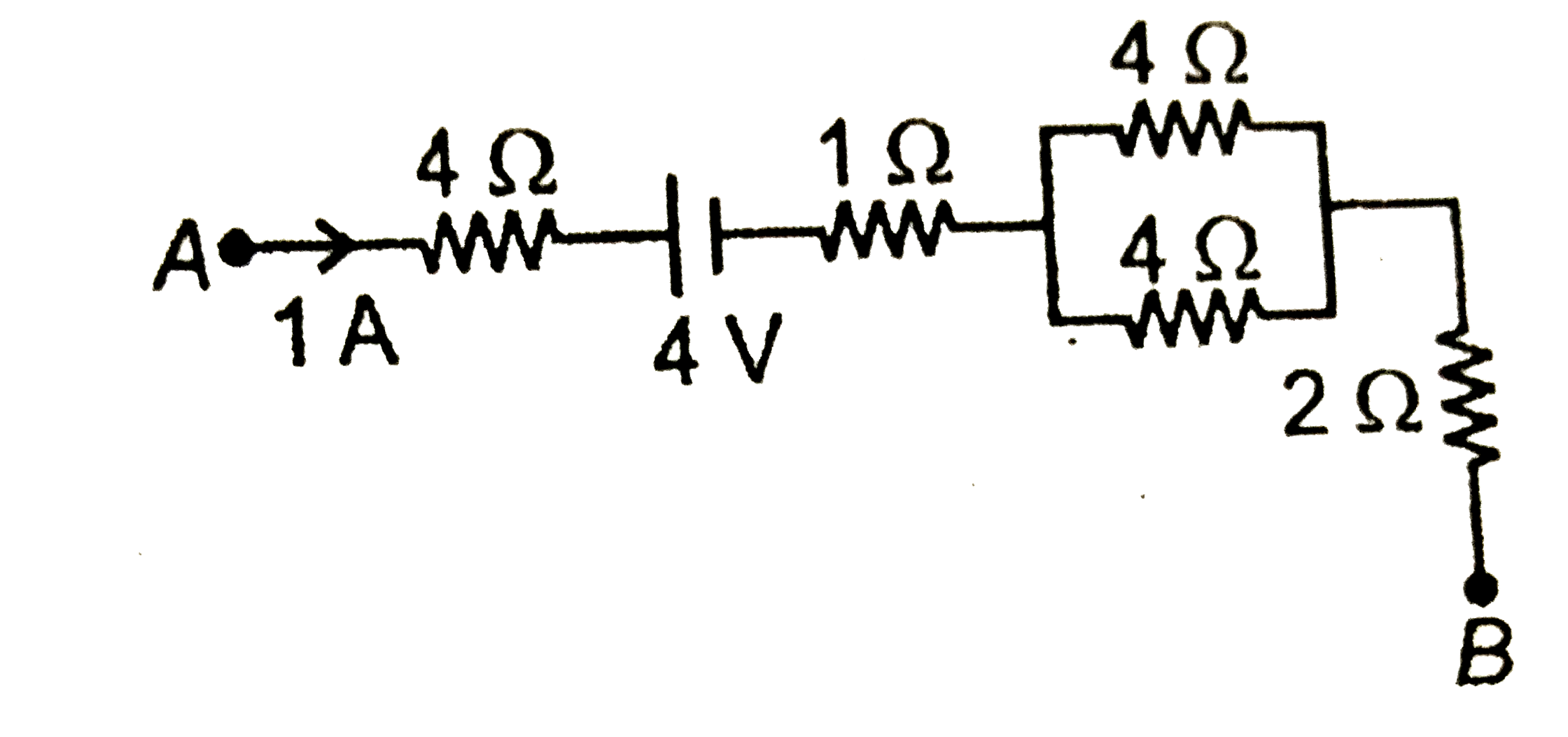 A9VB8VC15VD13V
Find the potential difference Va−Vbin the circutis shown in figure
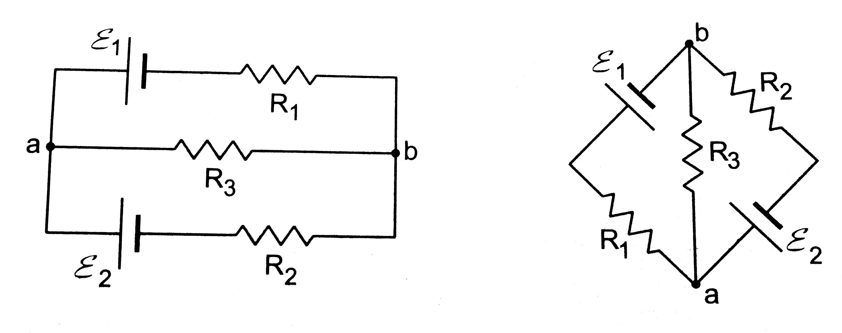
View SolutionPotential difference VB−VA in the network shown is
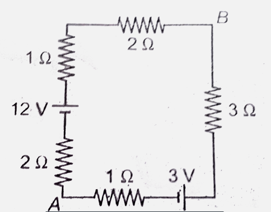
View SolutionFind the potential difference VA−VB between points A and B of the circuit shown in.
 .
.
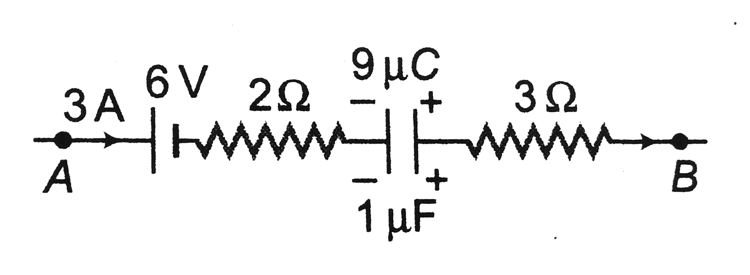
View SolutionThe potential difference VA−VB between points A and B for the circuit segment shown in figure at the given instant is
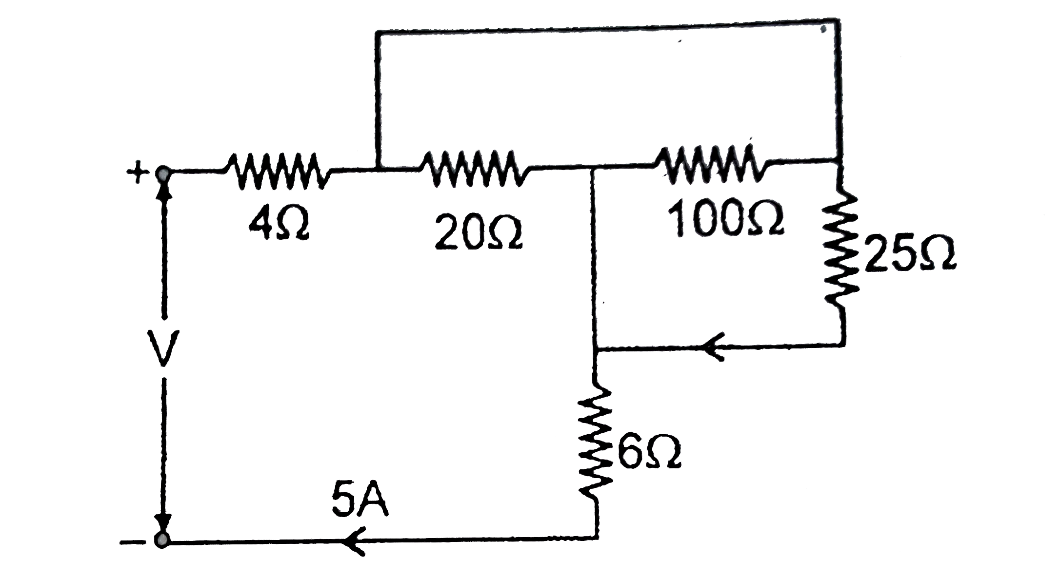
View SolutionIn the circuit, V is potential differences across the terminal as shwon in figure. Then the value of V is
View Solution

