The resistance of the rheostat shown in figure is 30(Ω). Neglecting the meter resistance,find the minimum and maximum currents through the ammeter as the rheostat is varied.
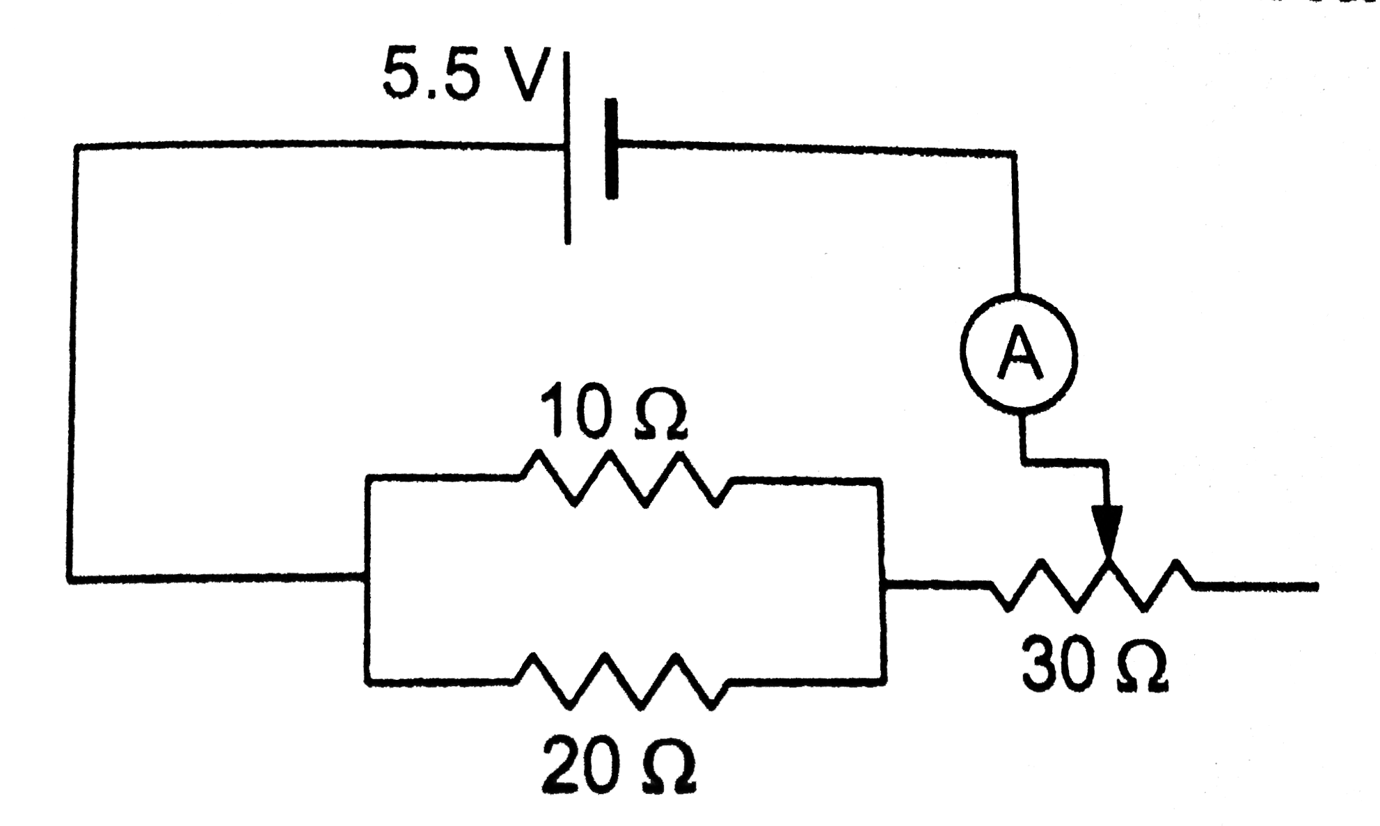
320=0.15A,3×5.520=0.83A
Topper's Solved these Questions
- CURRENT ELECTRICITYBook:MOTIONChapter:CURRENT ELECTRICITYExercise:EXERCISE -3 (Level -II) SECTION A- Definition of Current , Current Density , Drift Velocity
Explore 1 Video
- CURRENT ELECTRICITYBook:MOTIONChapter:CURRENT ELECTRICITYExercise:EXERCISE -3 (Level -II) SECTION B- Resistance & resistivity ,Ohms law +VI (Volt - Curr.) Characteristics + Colour Code + Temp . Dependence
Explore 6 Videos
- CURRENT ELECTRICITYBook:MOTIONChapter:CURRENT ELECTRICITYExercise:EXERCISE -3 (Level -I) SECTION C,D - Circuit theory , KCL & KVL, Battery , Grouping of cells
Explore 13 Videos
- CONSTRAINED MOTION Book:MOTIONChapter:CONSTRAINED MOTION Exercise:EXAMPLES
Explore 12 Videos
- ELASTICITYBook:MOTIONChapter:ELASTICITYExercise:EXERCISE -3
Explore 60 Videos
Similar Questions
Knowledge Check
The resistance of the shown in figure is 30Ω. Neglecting the ammeter resistacnce, the ratio os minimum and maximum currents through the ammeter, as the rheostat is varied, will be :
 A25B8315C943D1943
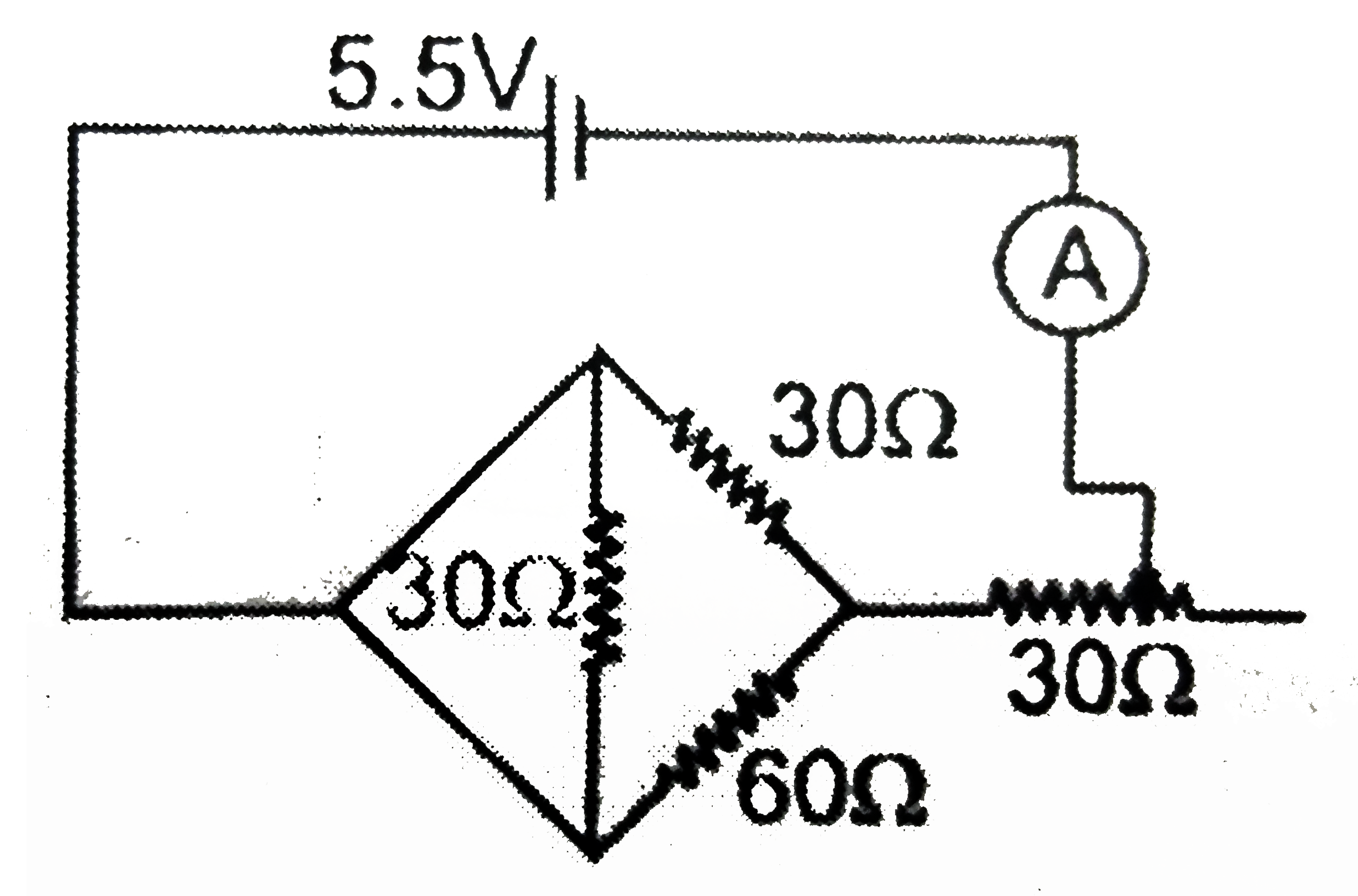
If each resistance in the figure is of 9Ω then reading of ammeter is
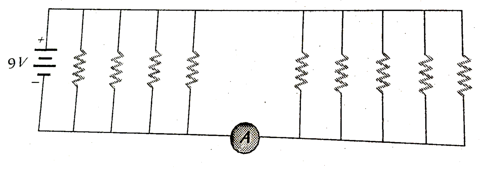 A√3B√2C1√2D1√3
If the reading of ammeter A3 in figure is 0.75 A. Neglecting the resistances of the ammeters, the reading of ammeter A2 will be :
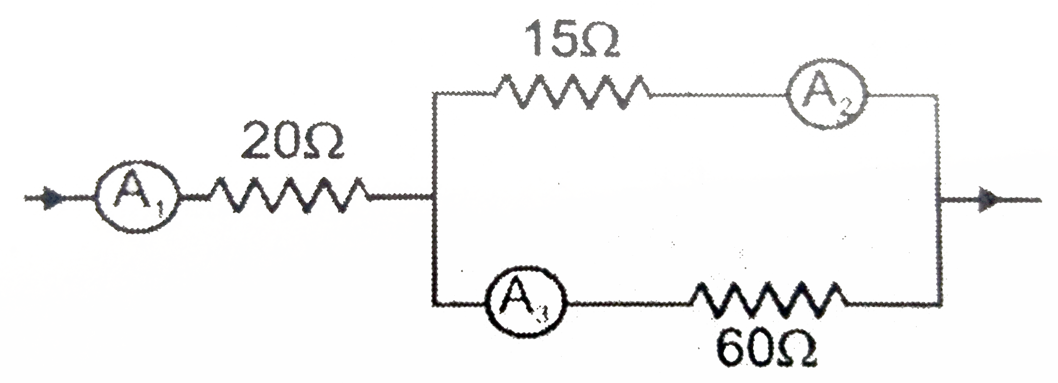 A1.5 AB0.125C4.5 AD0.25
Find the current l through then 10Ω resistance in the network shown in figure.
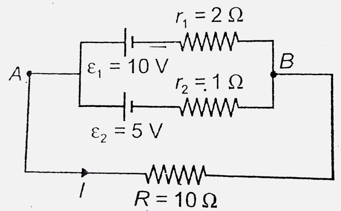
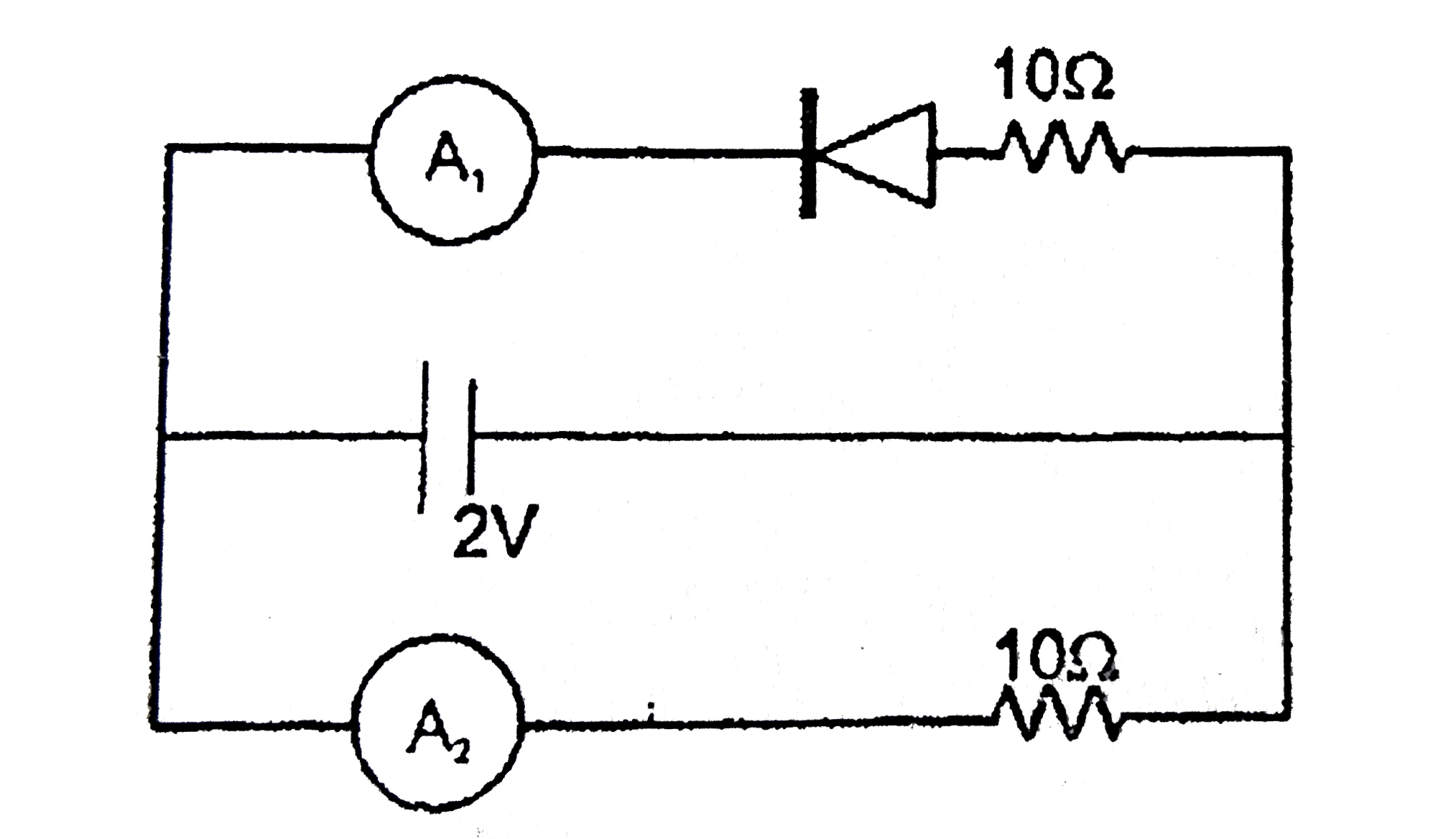
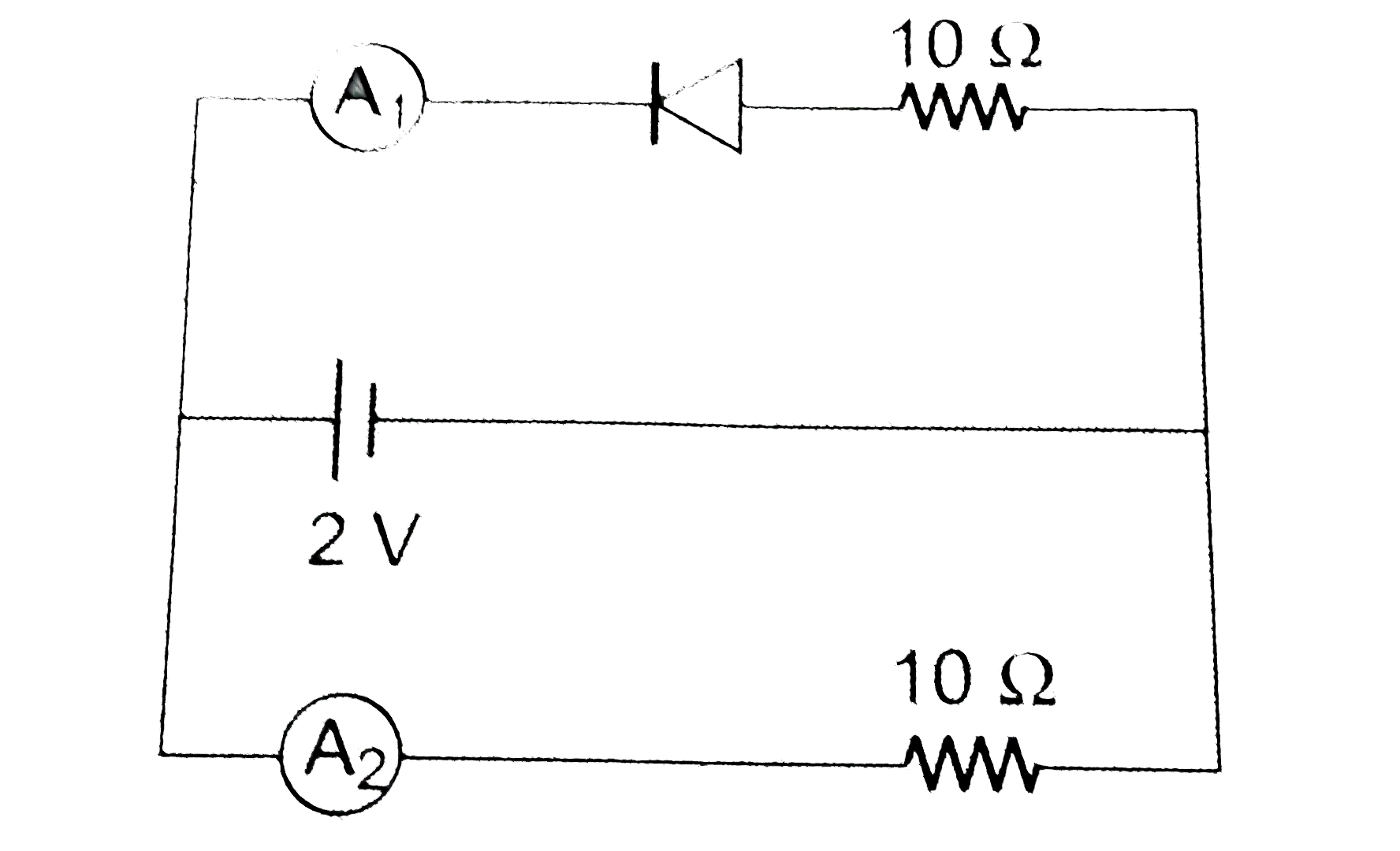
View Solution(a) What are the readings of the ammeters A1 and A2 shown in the figure.neglect the resistance of the meters.
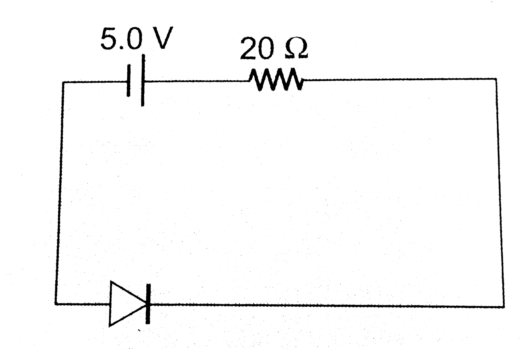
(b) Calculate the current through the circuit and the potential difference across the diode shown in the figure. The drift current fo the diode is 20μA.
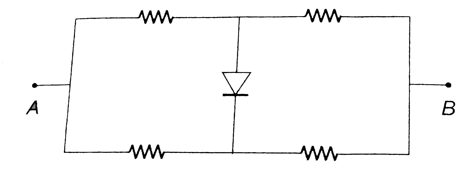
(c ) Each of the resistances shown in the figure has a value of 20Ω. find the equivalent resistance between A and B. Does it depend on whether the point A or B is at higher potential?
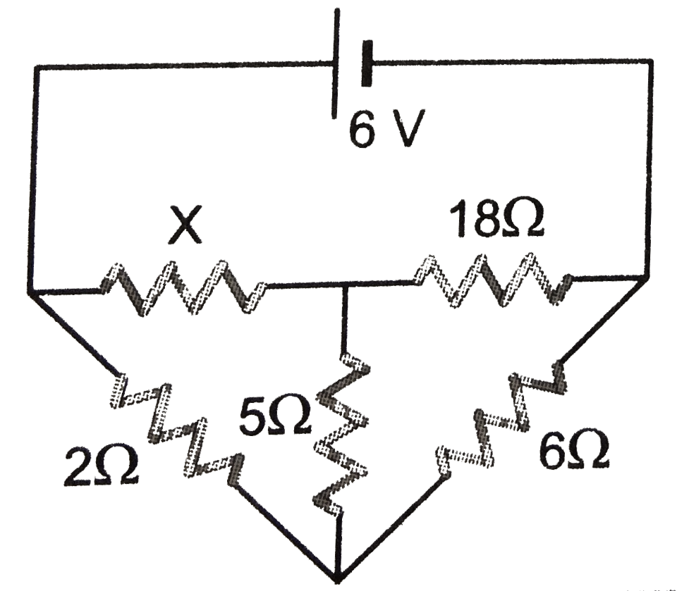
View SolutionFind out the magnitude of resistance X in the circuit shown in figure, When no current flows through the 5Ω resistance
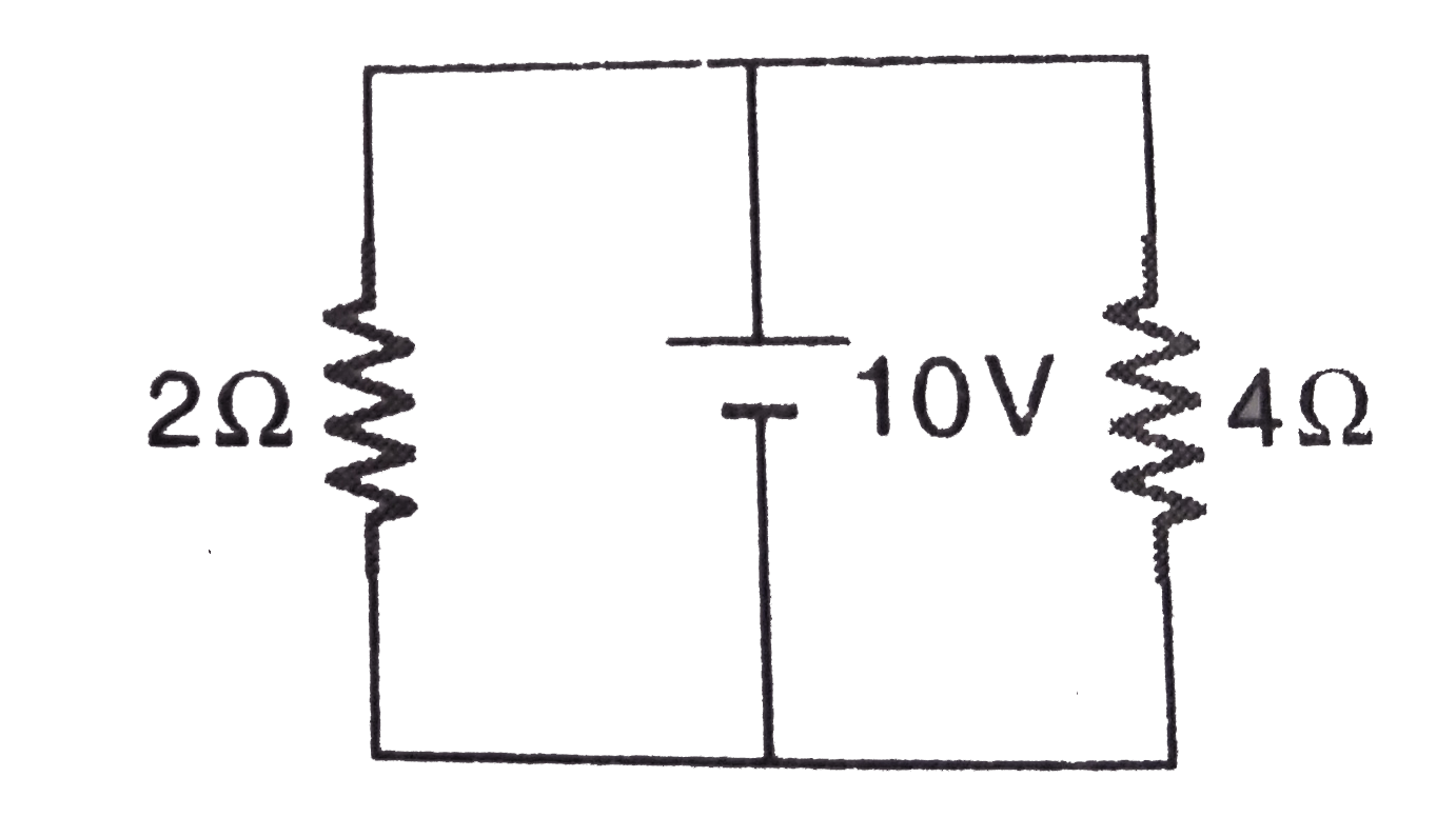
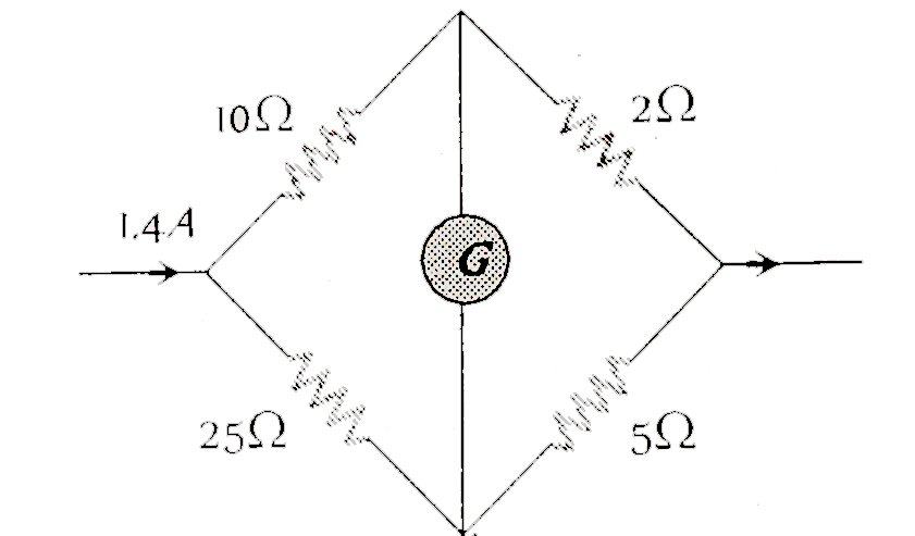
View SolutionIn the circuit shown in the figure, the current flowing in 2Ω resistance
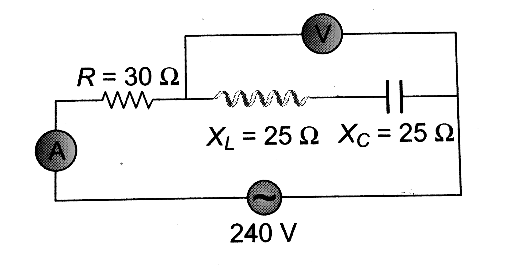
View SolutionIn the circuit shown in figure neglecting source resistance the voltmeter and ammeter reading will respectively, will be
View Solution
