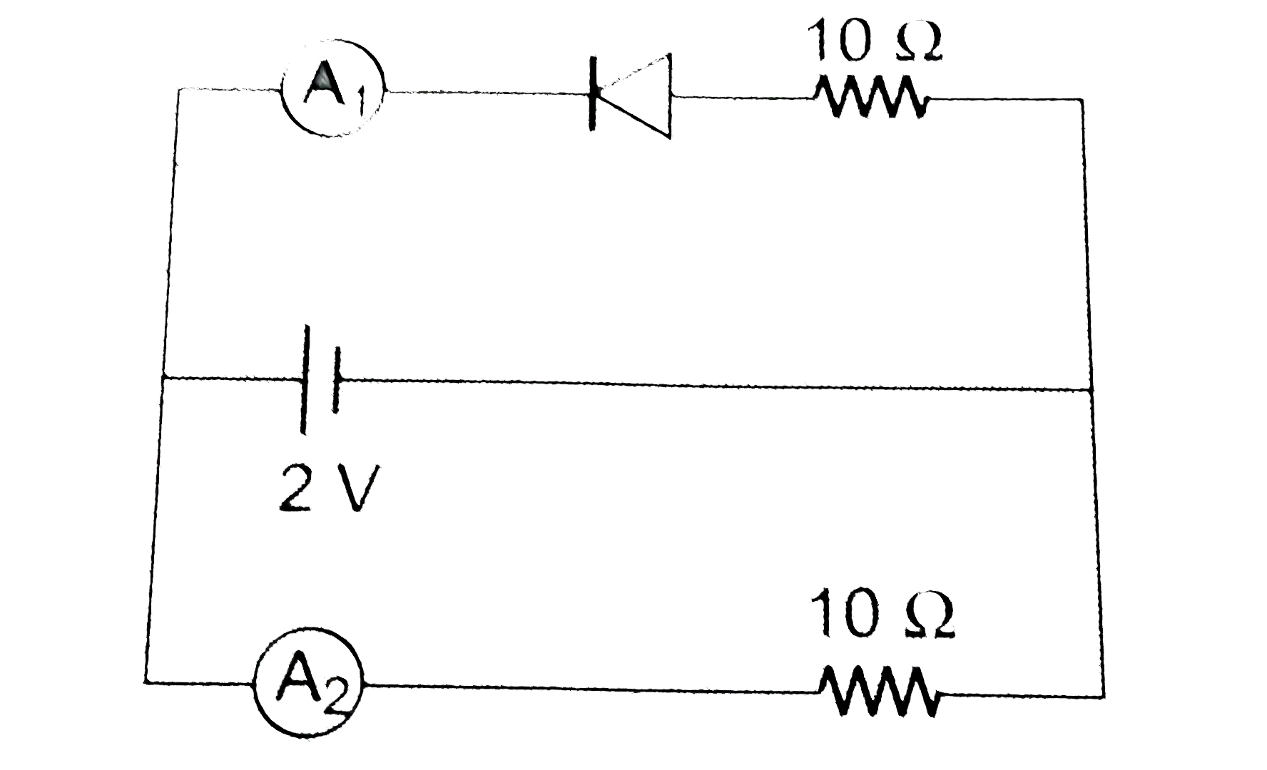
(a) What are the readings of the ammeters A1 and A2 shown in the figure.neglect the resistance of the meters.
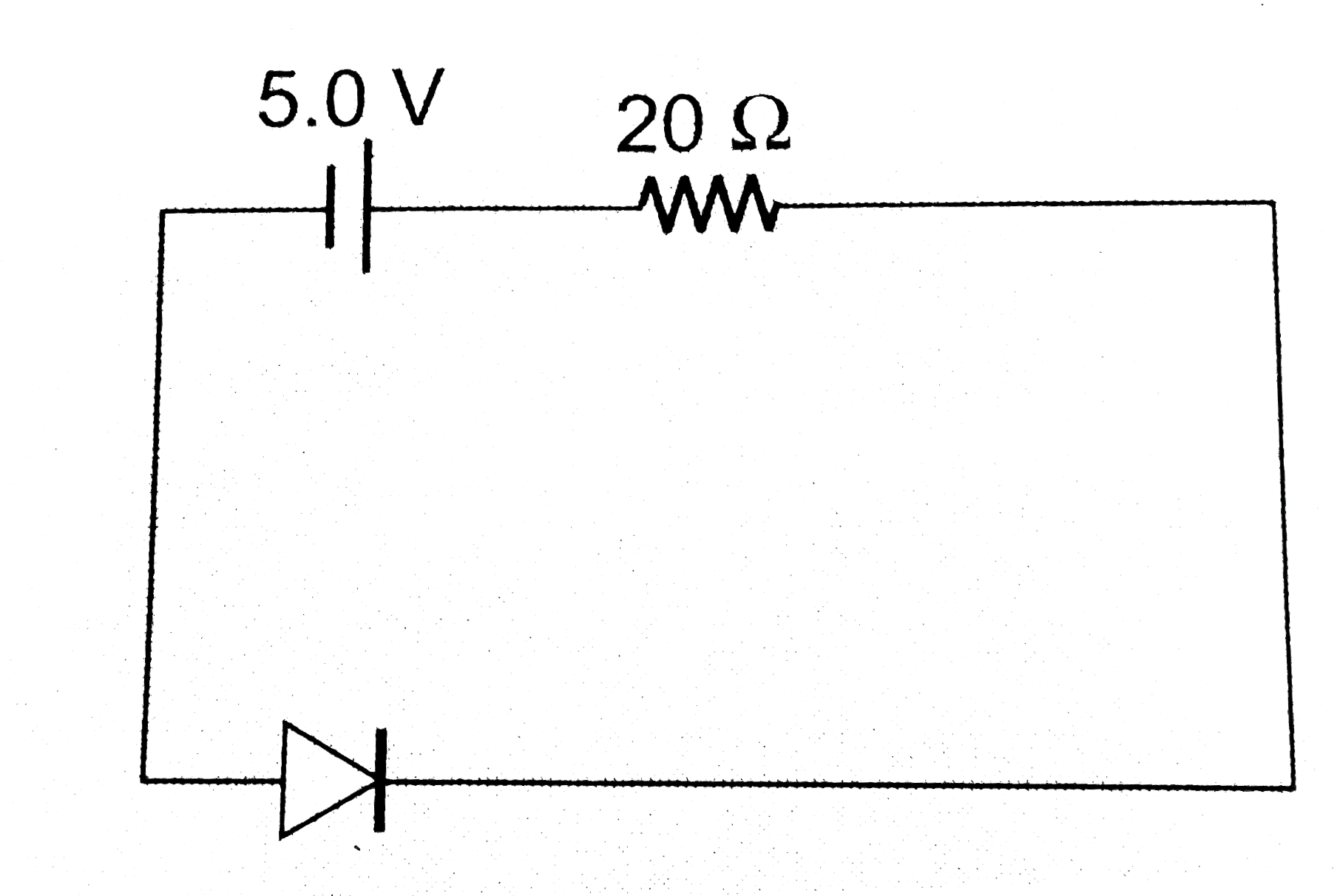
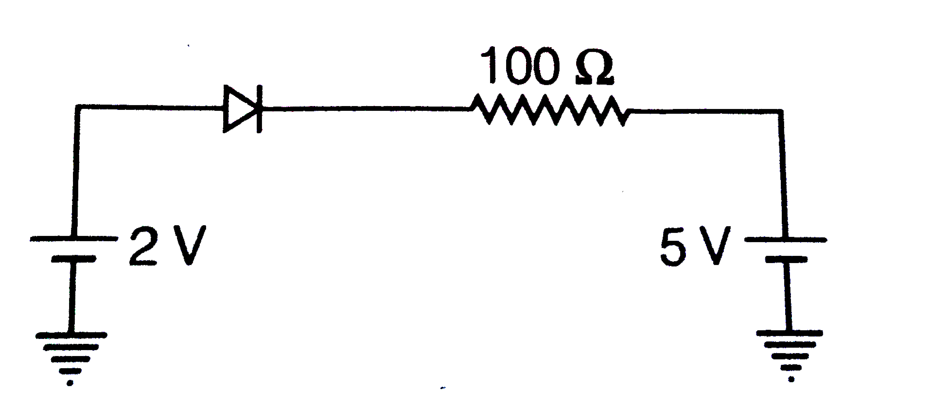
(b) Calculate the current through the circuit and the potential difference across the diode shown in the figure. The drift current fo the diode is 20μA.
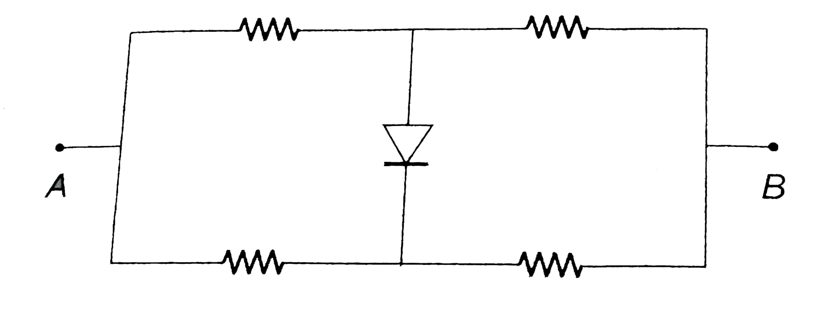
(c ) Each of the resistances shown in the figure has a value of 20Ω. find the equivalent resistance between A and B. Does it depend on whether the point A or B is at higher potential?
(a) 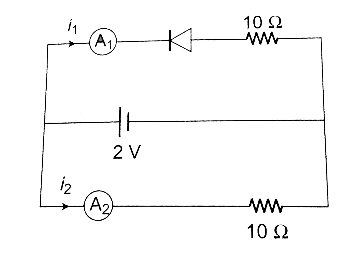
Diode is in reverse bias, i1=0
i2=210=0.2A
(b) 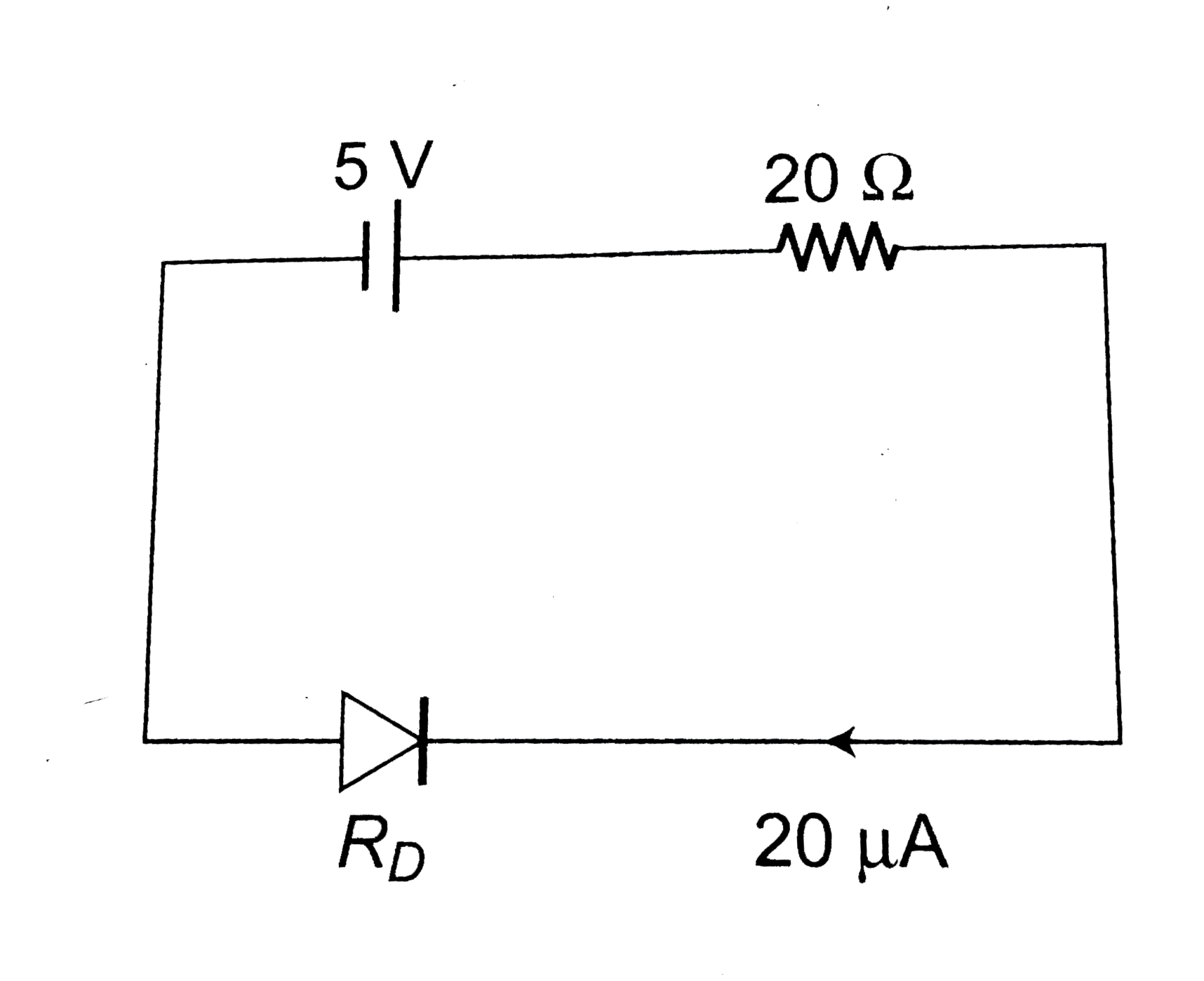
p.d. across 20Ω=20×10−6×20
=0.0004V
p.d. across diode=5−0.0004
=4.9996V
(c ) 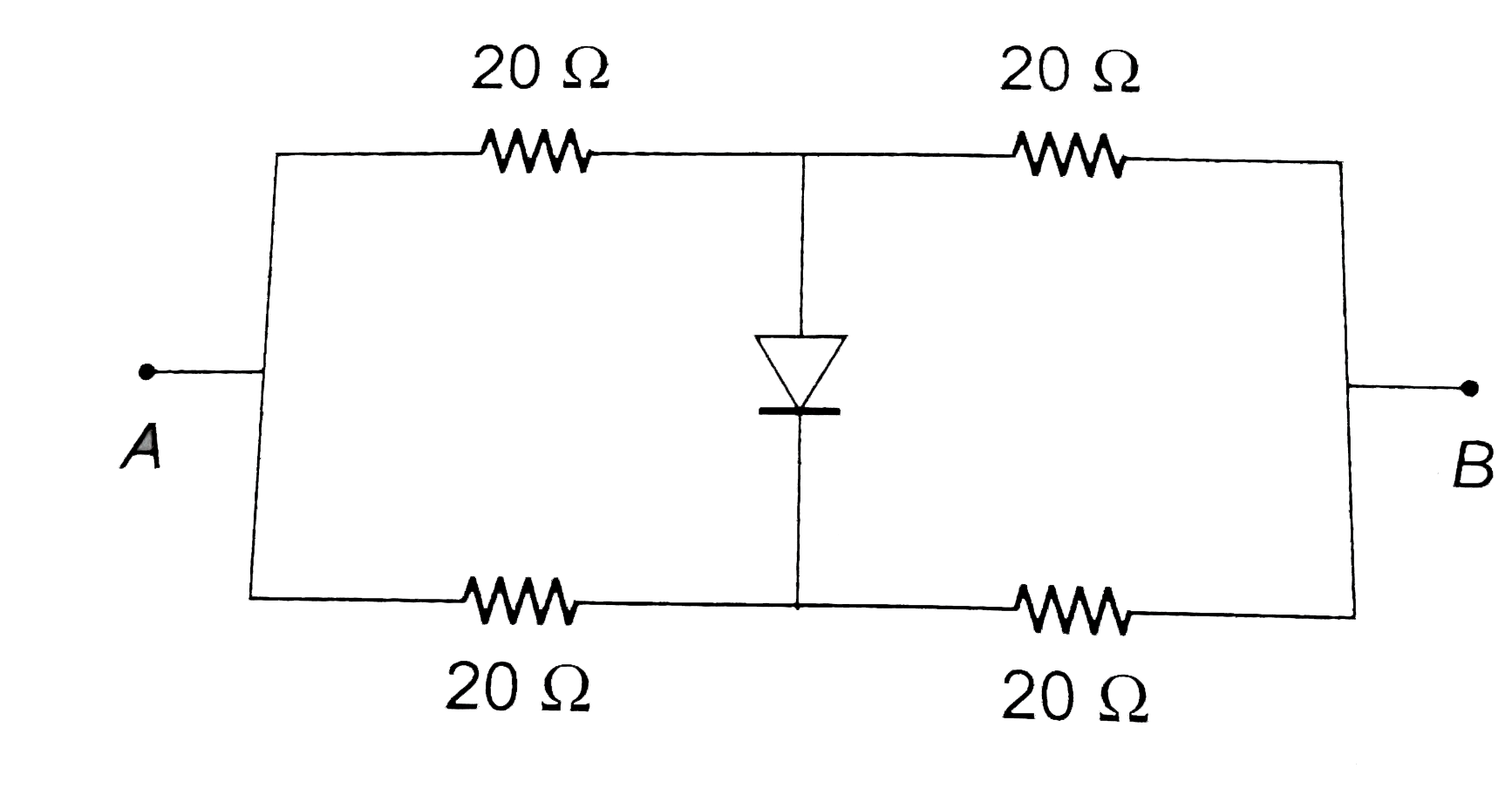
This is balanced wheatstone bridge.
Req=20Ω
Topper's Solved these Questions
- SEMICONDUCTORSBook:CP SINGHChapter:SEMICONDUCTORSExercise:Exercises
Explore 140 Videos
- REFRACTION OF LIGHT BY PLANE SURFACESBook:CP SINGHChapter:REFRACTION OF LIGHT BY PLANE SURFACESExercise:Exercises
Explore 110 Videos
- THERMAL AND ELECTRIC EFFECT oF CURRENTBook:CP SINGHChapter:THERMAL AND ELECTRIC EFFECT oF CURRENTExercise:Exercises
Explore 101 Videos
Similar Questions
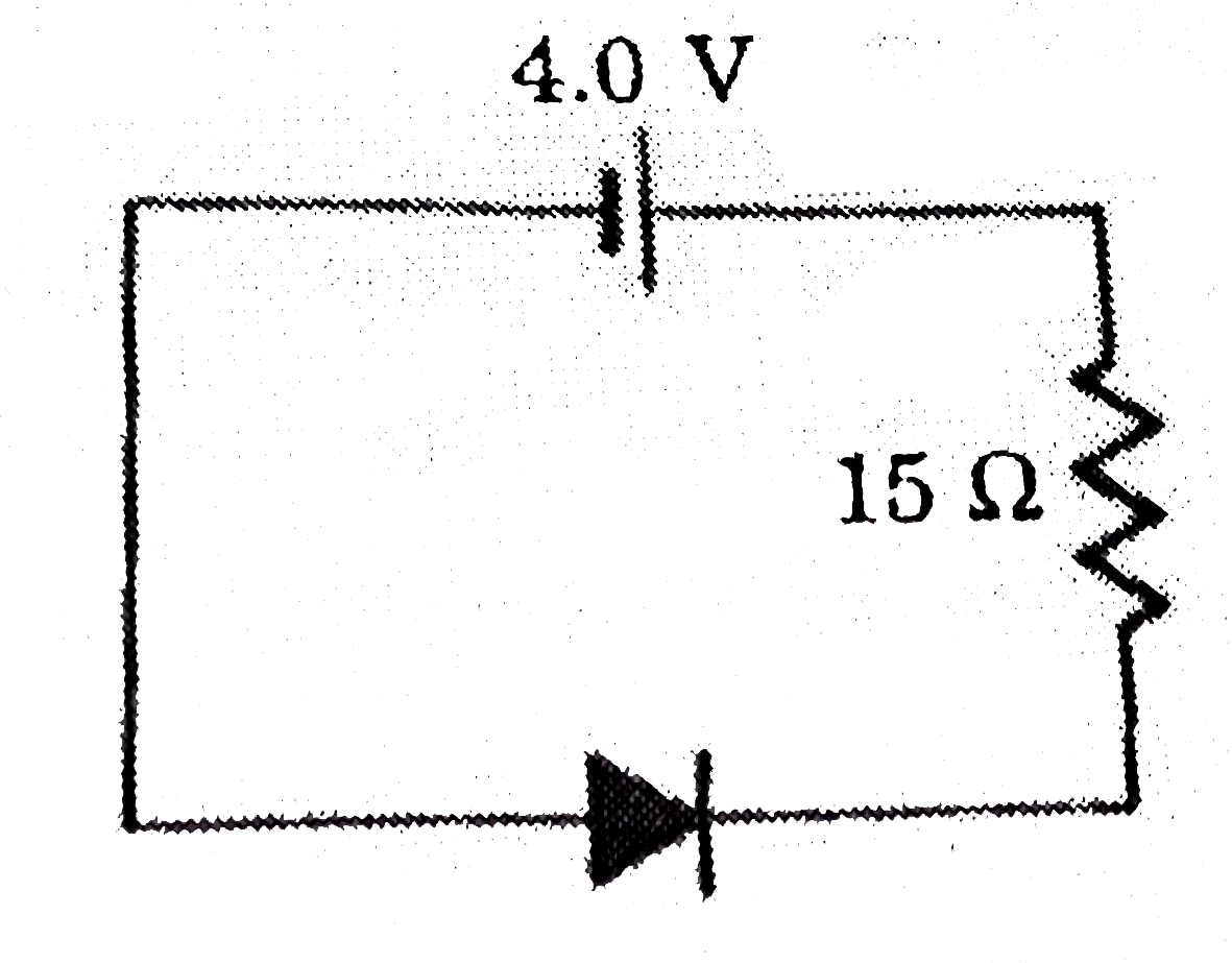
Find the current through the circuit and the potential difference across the diode shown in fig. The drift current for the diode is 20μA
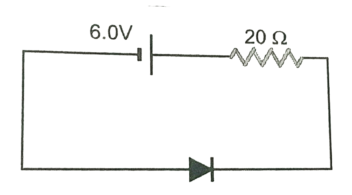
View SolutionCalculate the current through the circuit and the potential difference across the diode shown in Fig. The drift current for the diode is 30μA.
View Solution
Knowledge Check
Each resistance shown in figure is 2Ω. The equivalent resistance between A and B is
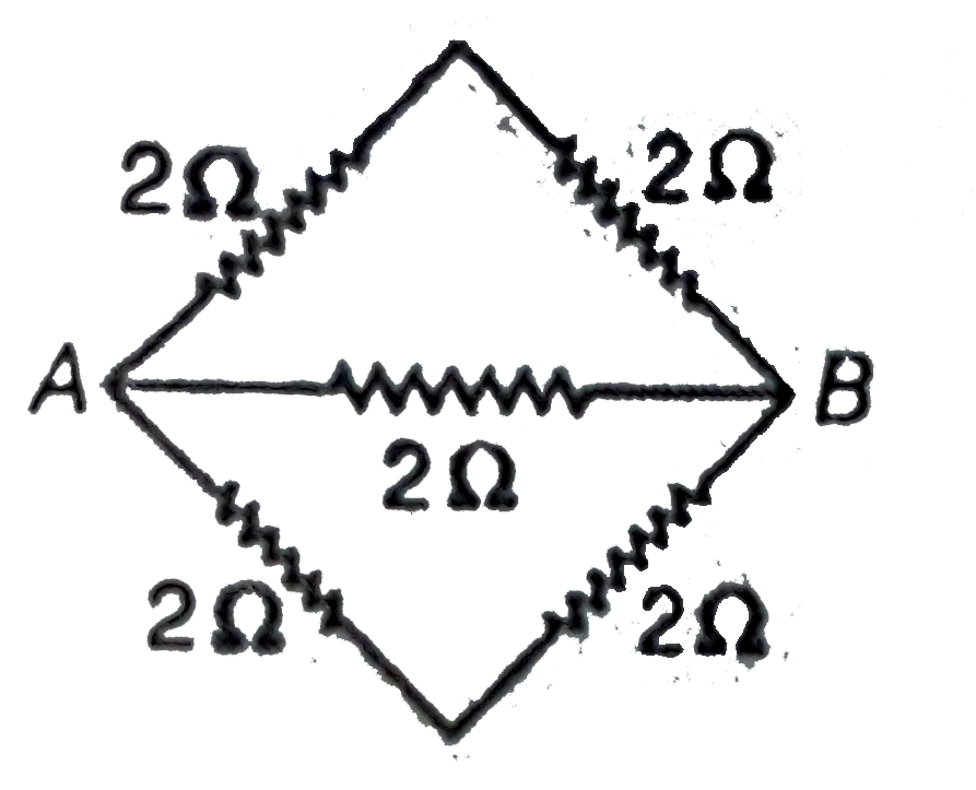 A2ΩB4ΩC8ΩD1Ω
The equivalent resistance of the circuit shown in the figure is
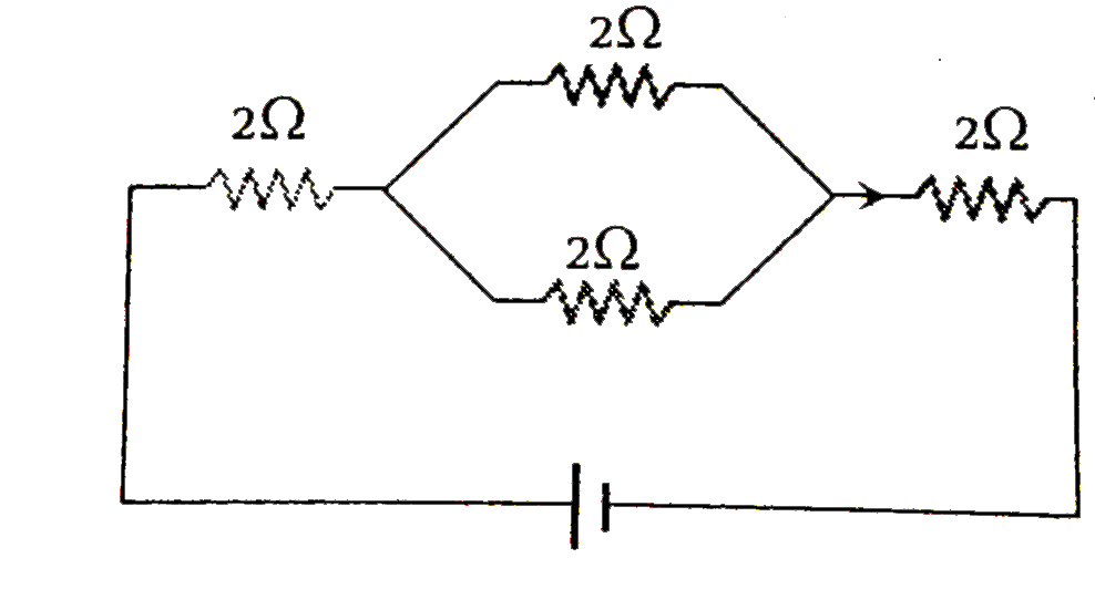 A8ΩB6ΩC5ΩD4Ω
In the figure shown, current passing through the diode is
 A0.1AB0.02ACzeroD0.01A
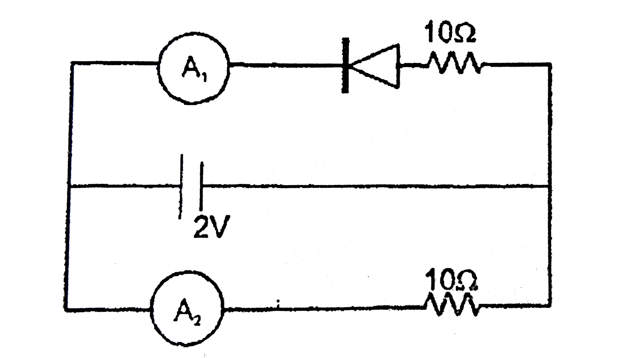
What are the readint of the ammeters A1 and A2 shown in figure. Neglect the resistance of the maters.
View SolutionEach resistance is of 1Ω in the circuit diagram shown in figure. Find out equivalent resistance between A and B.
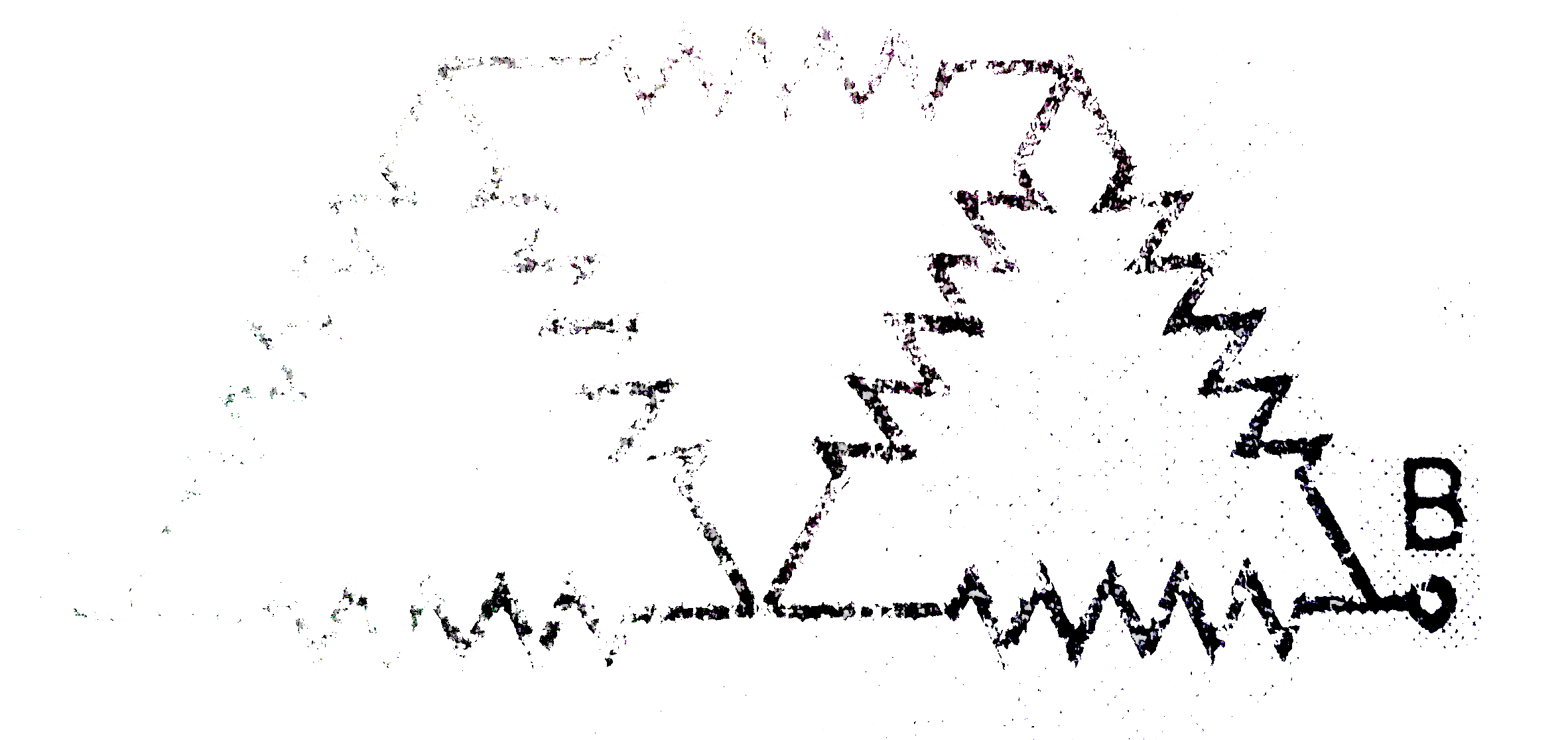
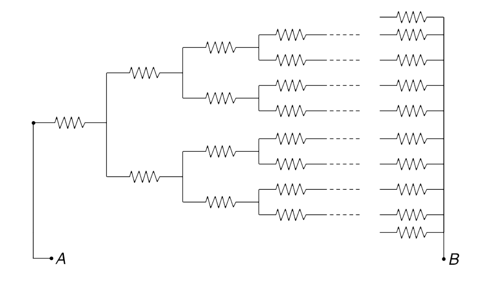
View SolutionAn infinite network of resistances has been made as shown in the figure. Each resistance is R. find the equivalent resistance between A and B.
View SolutionCurrent through the ideal diode as shown in the figure is
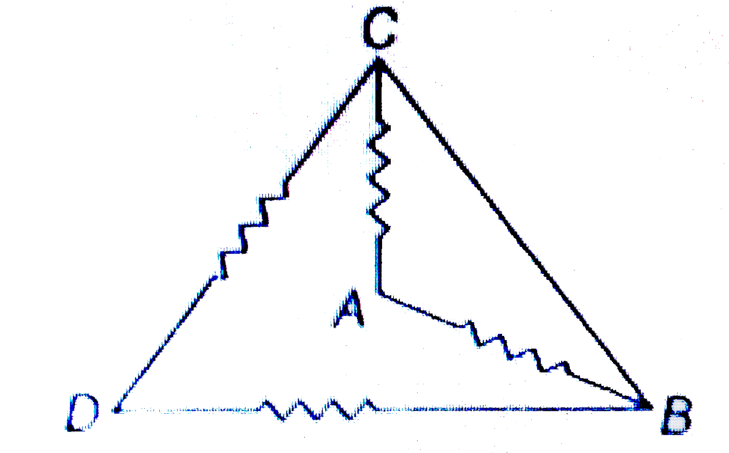
View SolutionEach resistance of the circuit shown in figure is r. The equivalent resistance between A and B is
View Solution