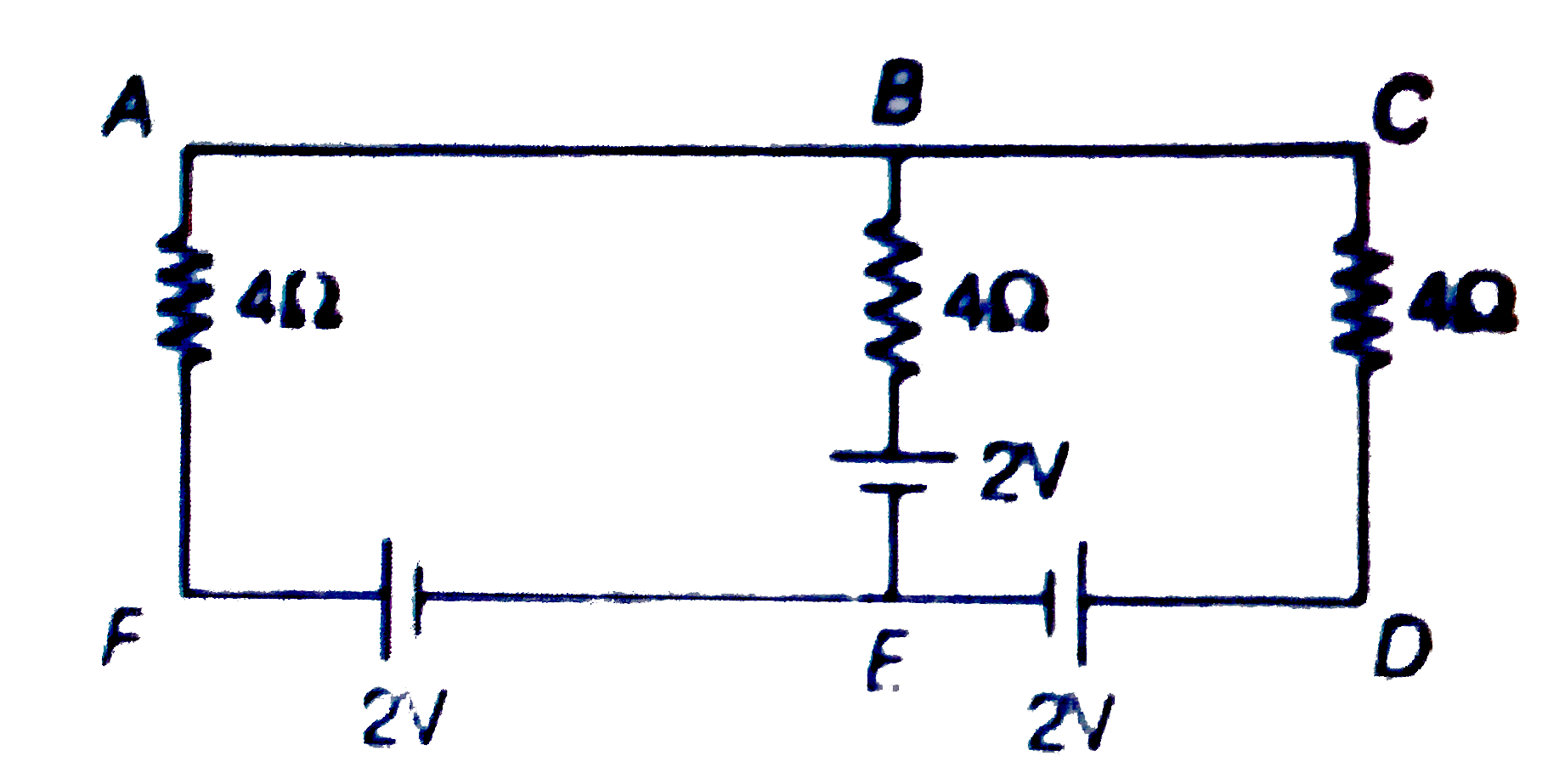
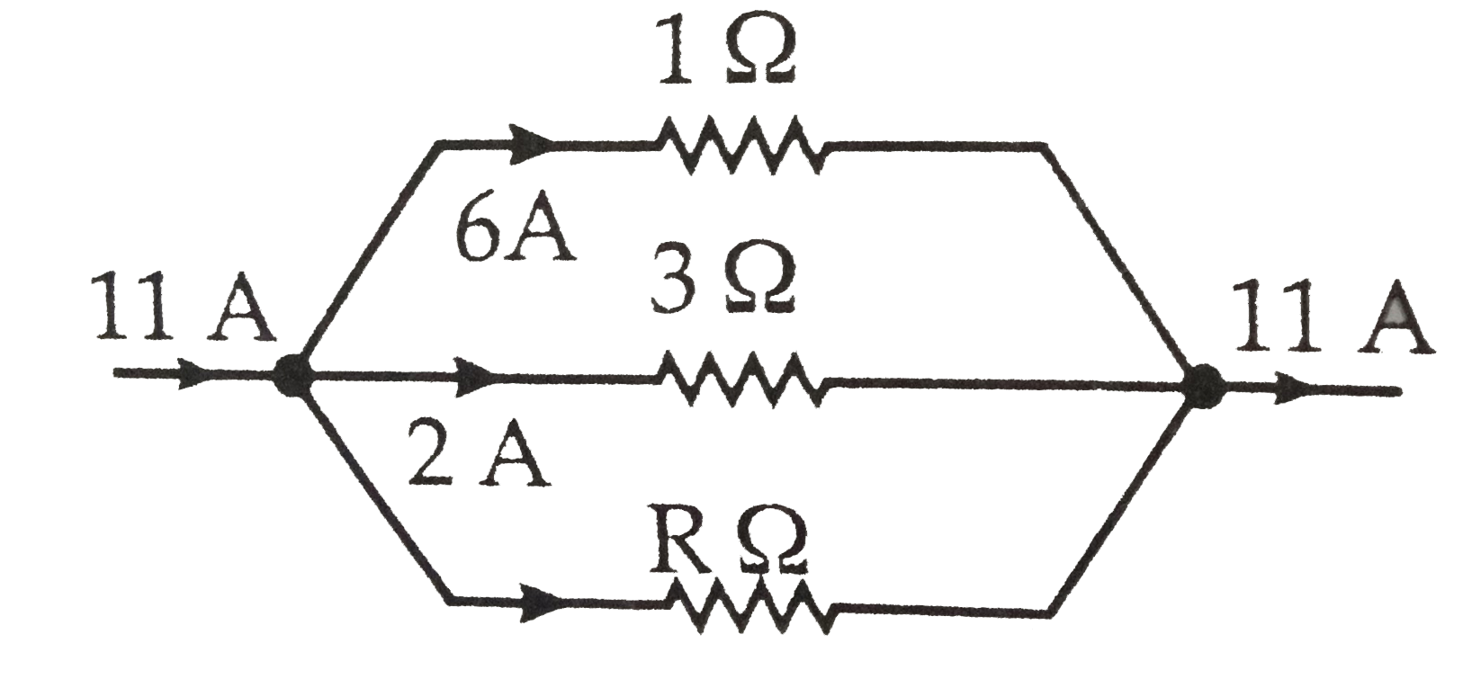
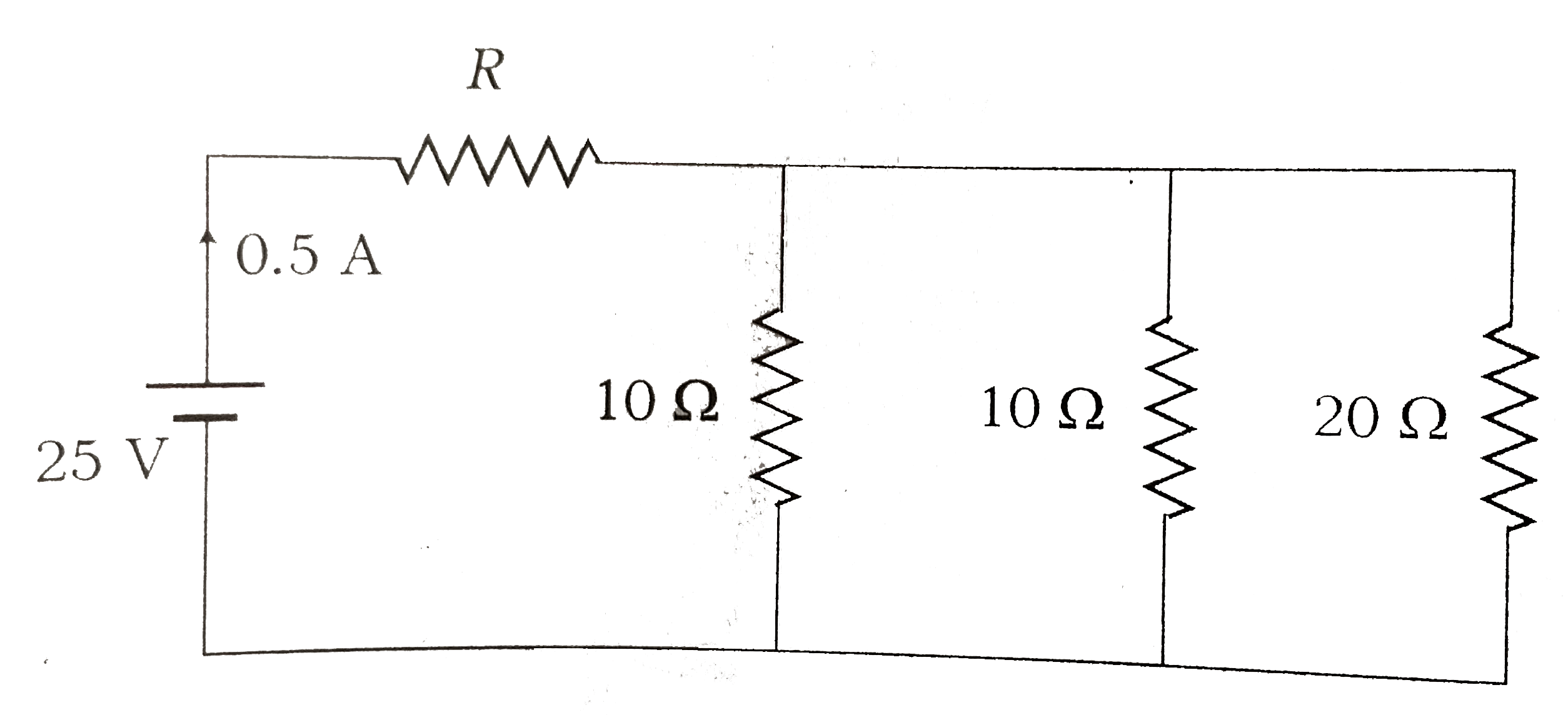
For the circuit shown in figure,
A
resistance R=46Ω
B
current through 20Ω resistance is 0.1A
C
potential difference across the middle resistance is 2 V
D
All of the above are true
Video Solution
Text Solution
The correct Answer is:D
|
Answer
Step by step video, text & image solution for For the circuit shown in figure, by Physics experts to help you in doubts & scoring excellent marks in Class 12 exams.
Updated on:21/07/2023Topper's Solved these Questions
- CURRENT ELECTRICITYBook:DC PANDEYChapter:CURRENT ELECTRICITYExercise:Match the columns
Explore 4 Videos
- COMMUNICATION SYSTEMBook:DC PANDEYChapter:COMMUNICATION SYSTEMExercise:Subjective
Explore 11 Videos
- ELECTROMAGNETIC INDUCTIONBook:DC PANDEYChapter:ELECTROMAGNETIC INDUCTIONExercise:Medical entrances gallery
Explore 25 Videos
Similar Questions
Knowledge Check
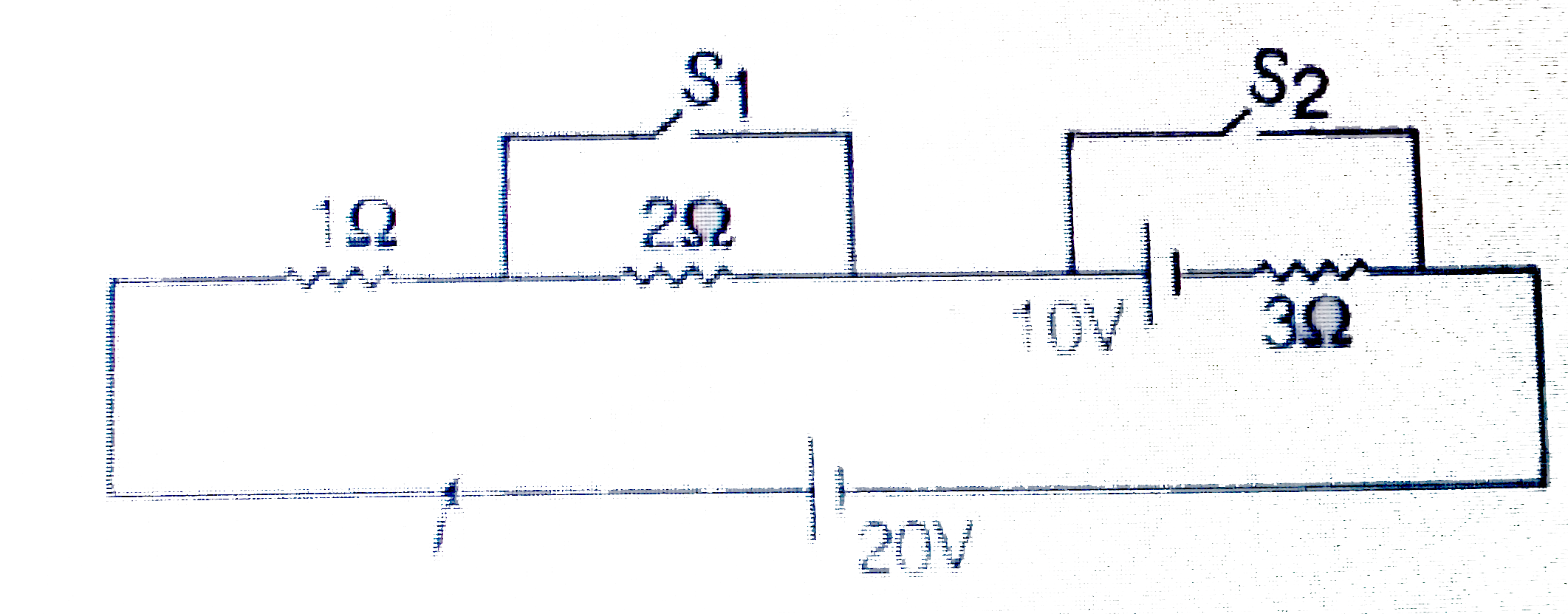
In the circuit shown in figure,
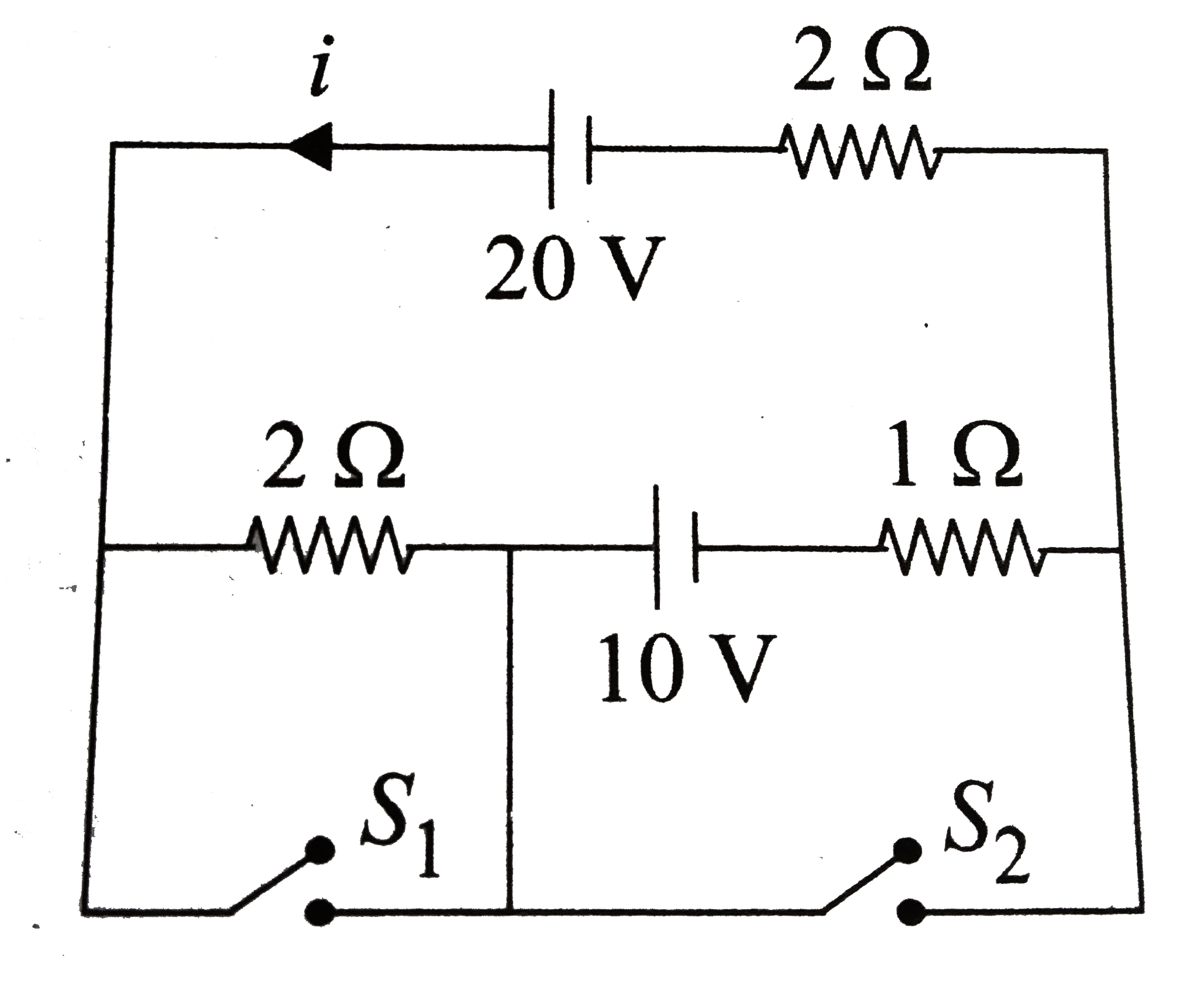 Ai=53A when S1 is closed and S2 is openBi=5A when S1 is open S2 is closedCi=2A when S1 and S2 both are openDi=10 A when both S1 and S2 are closed
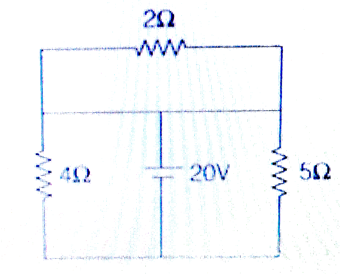
In the circuit shown in figure
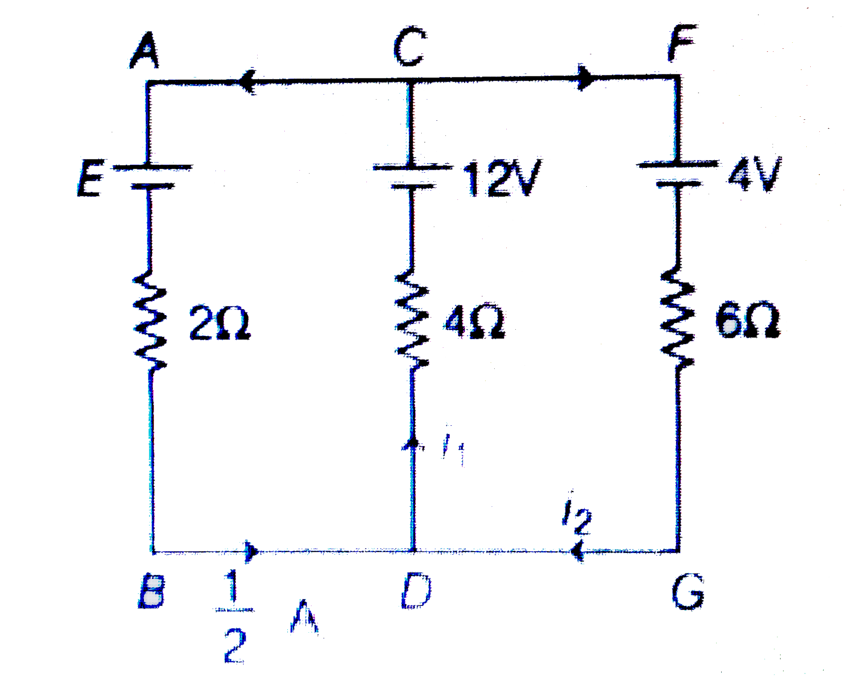 AE = 6.6 VBi1=1.1ACi2=0.5ADE = 4.4 V
In the circuit shown in figure
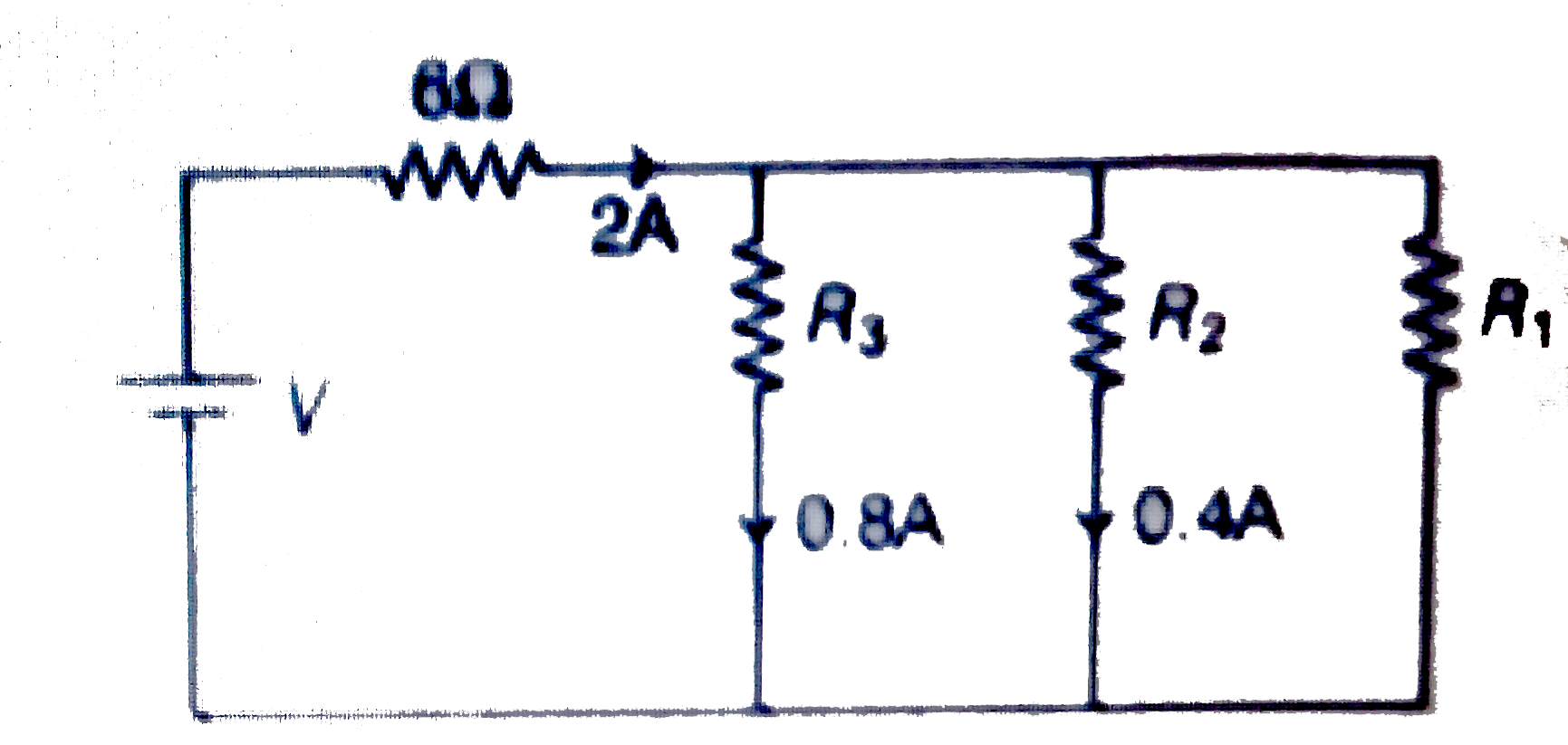 AV = 10 VBR1=10ΩCR2=20ΩDnet resistance of the circuit is 10Ω


