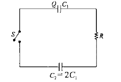
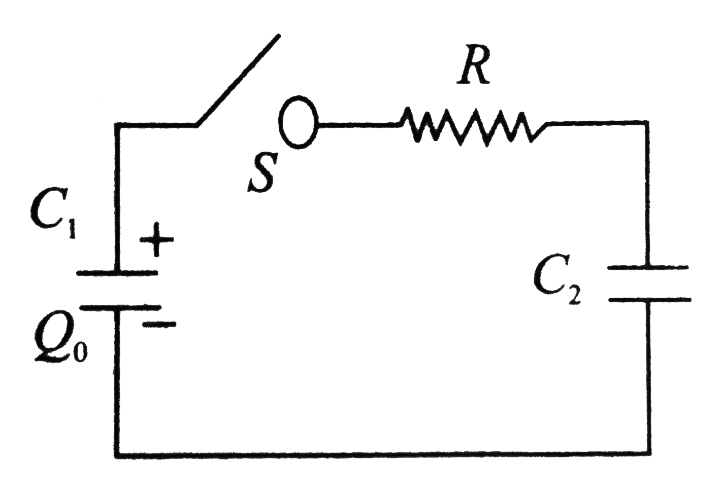
Two capacitors are connected in a circuit with a switch between them as shown in the figure- 3.302. Initially the switch is open and holds charge Q. The switch is closed. In steady state, the charge on the two capacitors will be given as :
The correct Answer is:B
Step by step video, text & image solution for Two capacitors C_(1) and C_(2) = 2C_(1) are connected in a circuit with a switch between them as shown in the figure- 3.302. Initially the switch is open and C_(1) holds charge Q. The switch is closed. In steady state, the charge on the two capacitors will be given as : by Physics experts to help you in doubts & scoring excellent marks in Class 12 exams.
Updated on:21/07/2023Topper's Solved these Questions
- ELECTROSTATIC POTENTIAL AND CAPACITORSBook:DC PANDEYChapter:ELECTROSTATIC POTENTIAL AND CAPACITORSExercise:(B) Chapter exercises
Explore 20 Videos
- ELECTROSTATIC POTENTIAL AND CAPACITORSBook:DC PANDEYChapter:ELECTROSTATIC POTENTIAL AND CAPACITORSExercise:(C) Chapter exercises
Explore 50 Videos
- ELECTROSTATIC POTENTIAL AND CAPACITORSBook:DC PANDEYChapter:ELECTROSTATIC POTENTIAL AND CAPACITORSExercise:Check point 2.5
Explore 20 Videos
- ELECTROMAGNETIC WAVESBook:DC PANDEYChapter:ELECTROMAGNETIC WAVESExercise:Sec C
Explore 22 Videos
- ELECTROSTATICSBook:DC PANDEYChapter:ELECTROSTATICSExercise:Medical entrances gallery
Explore 37 Videos
Similar Questions
In the circuit shown in figure initially the switch is opened. The switch is closed now.
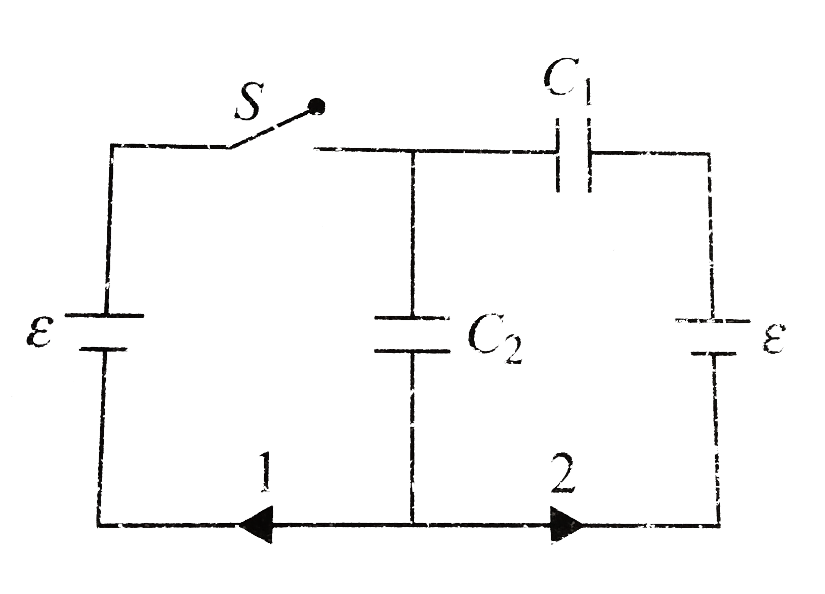
The charge that will flow in direction 2 is
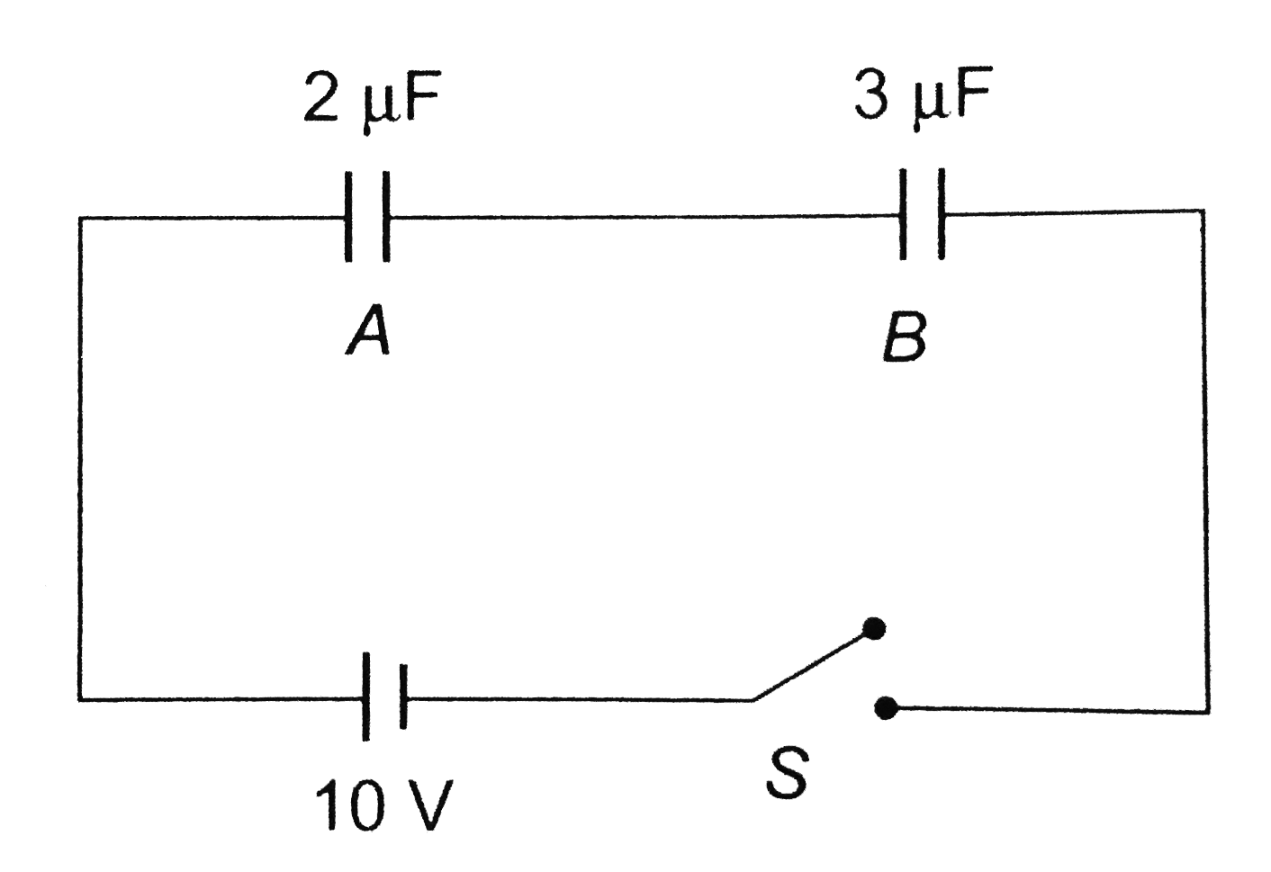
View SolutionTwo capacitors A and B are connected in series with a battery as shown in the figure. When the switch S is closed and the two capacitors get charged fully, then
View Solution
Knowledge Check
The circuit is in a steady state.
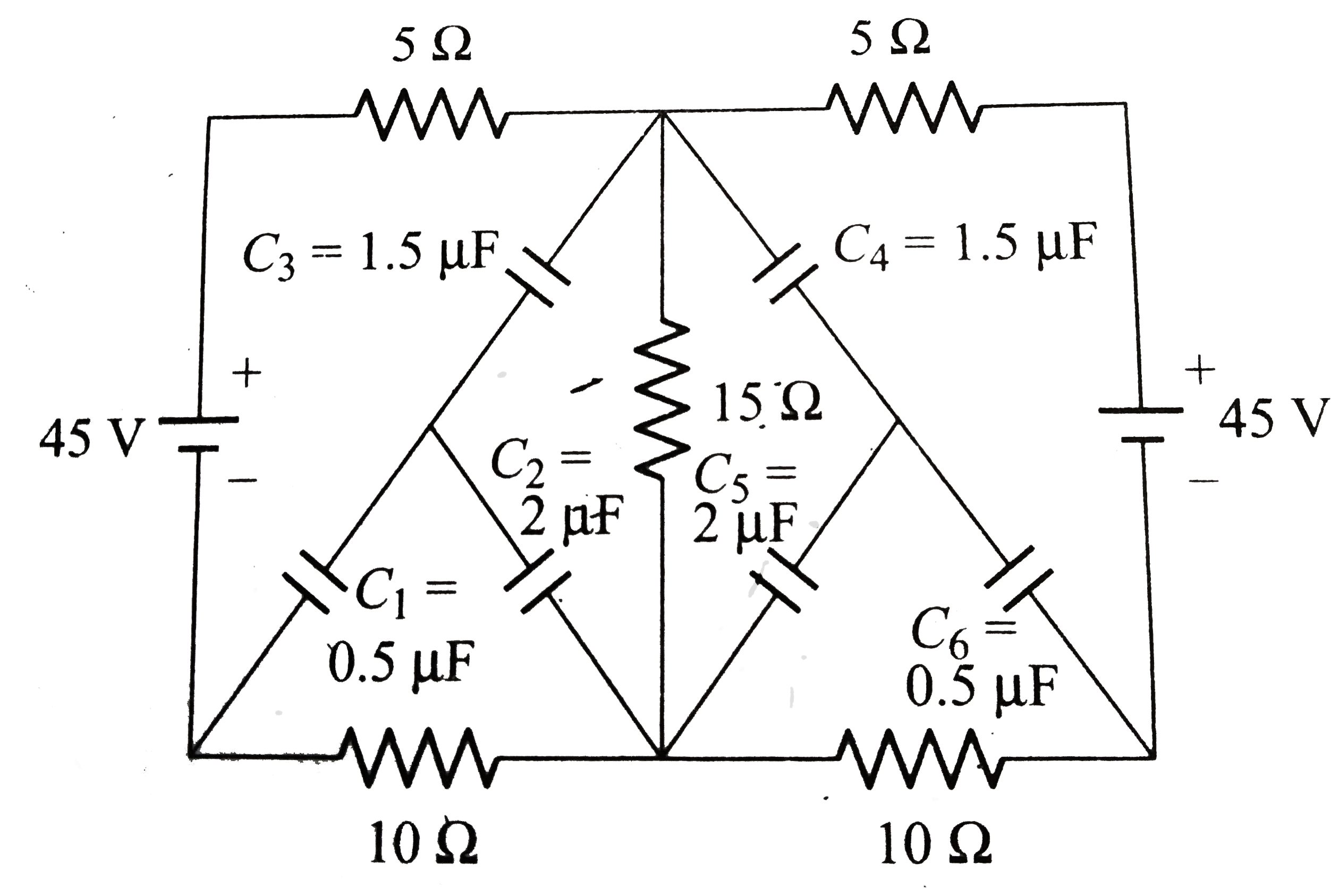
The charge in capacitor C1 isA20μCB30μCC40μCD10μCIn given circuit, switch S is closed at t=0 . The charge on the capacitor ar steady state will be
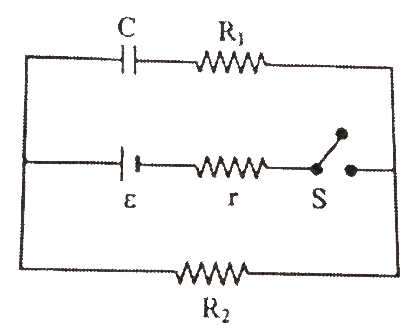 ACεR1r+R1BCεR2r+R2CCεR2r+R1DCεR1r+R2
In the circuit shown in figure initially the switch is opened. The switch is closed now.
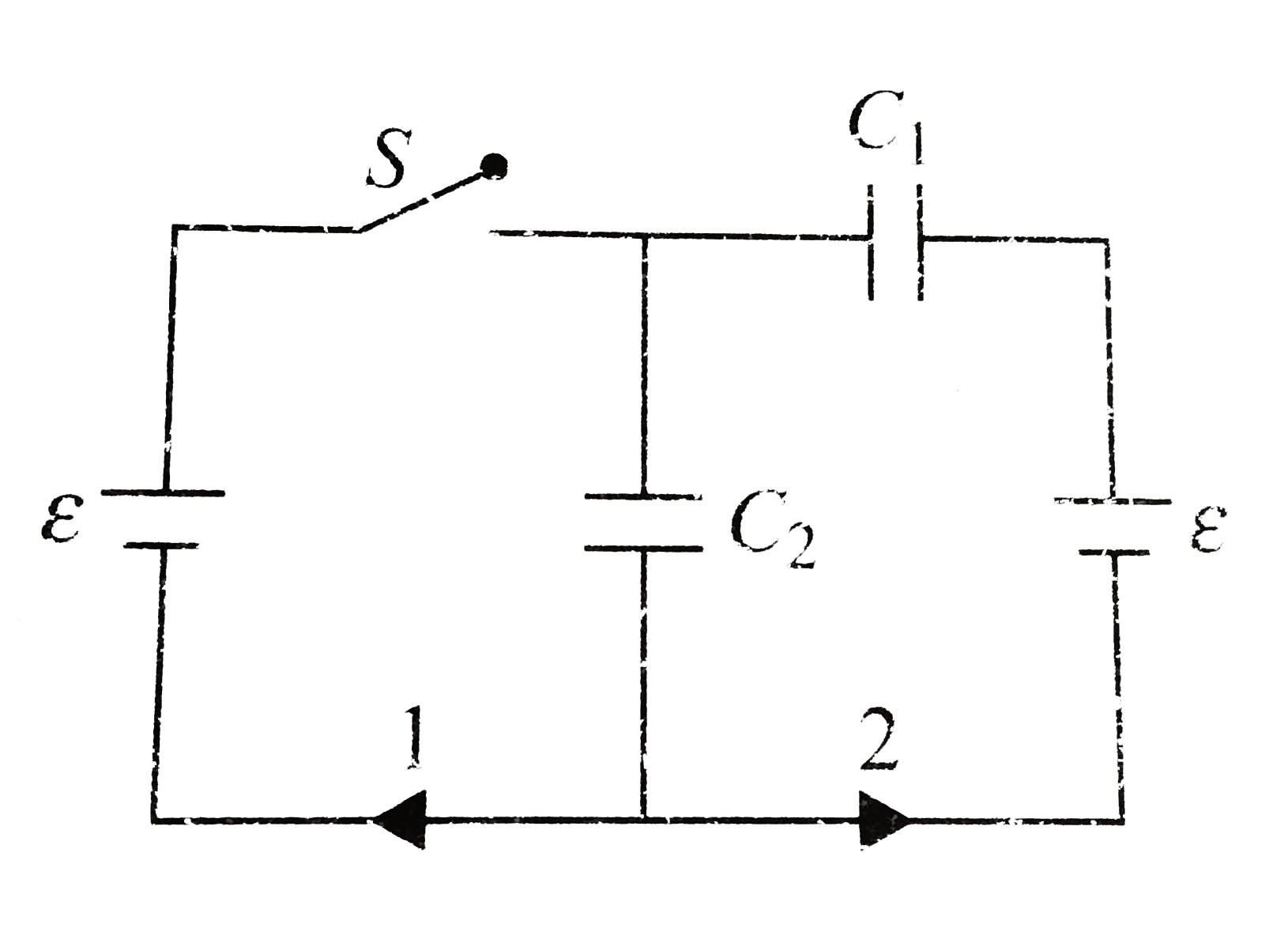
The charge that will flow in direction 1 isA−C22εC1+C2B−(C1C2C1+C2)εCC21εC1+C2DC2ε
Two capacitors C1 and C2 are charged to same potential V, but with opposite polarity as shown in the figure. The switches S1 and S2 are then closed

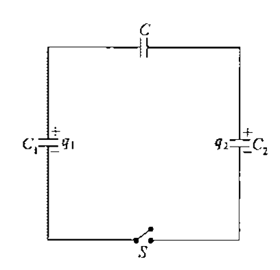
View SolutionTwo capacitor C1 and C2, charged with chargesq1 and q2 then these are connected in series with an uncharged capacitor C, as shown in figure. As the switch S is closed :
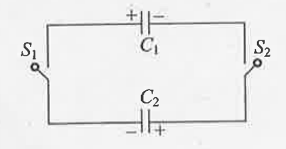
View SolutionTwo capacitors C1andC2 are charged to the same potential V, but with opposite polarity as shown in the figure. The switch S1andS2 are then closed.
View SolutionTwo capacitorsC1=4μFandC2=2μF are charged to same potential V = 500 Volt, but with opposite polarity as shown in the figure. The switches S1andS2are closed.
View SolutionIn the circuit shown, the capacitor C1 is initially charged with charge q0. The switch S is closed at time t = 0 . The charge on C2 after time t is
View Solution

