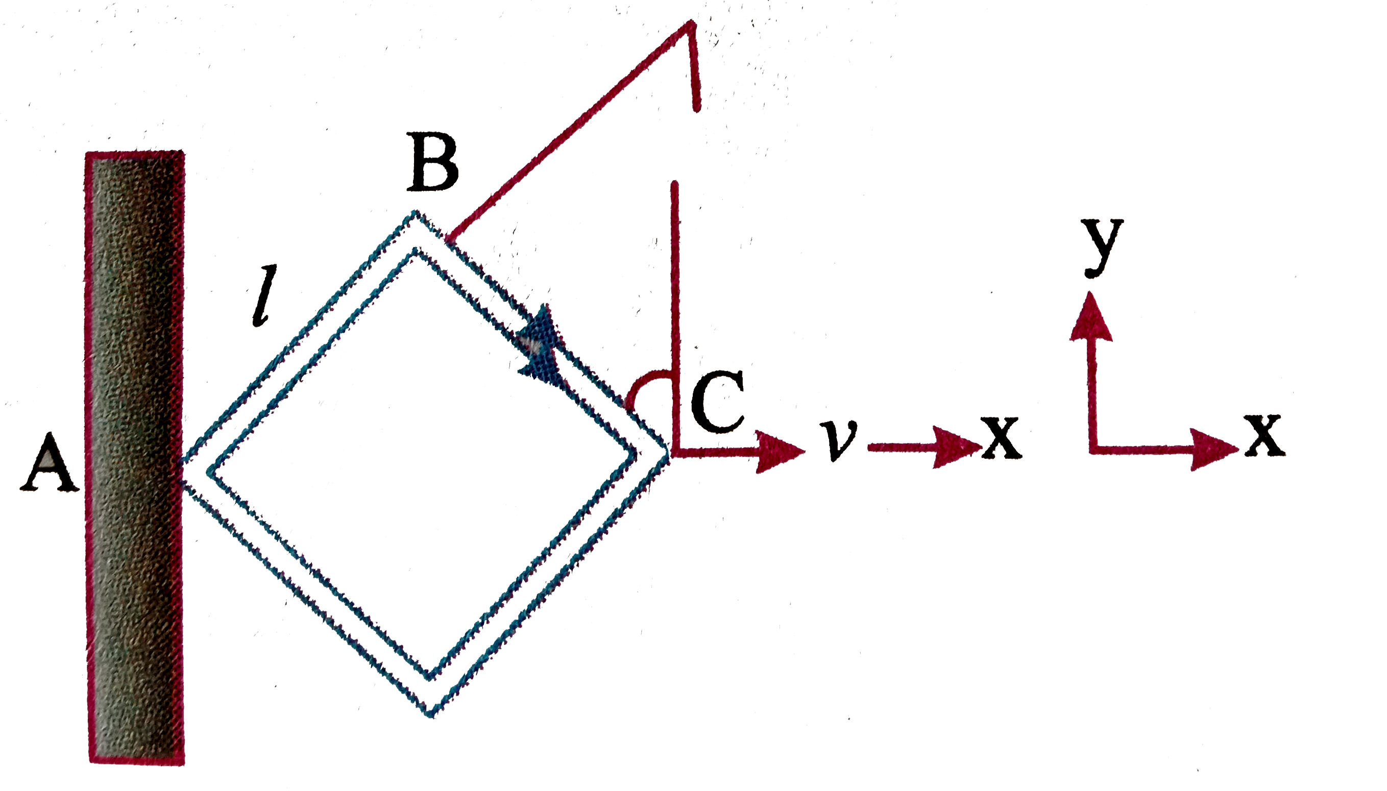
Four rods of side length have been hinged to form a rhombus. Vertex is fixed to a rigid support, vertex is being moved along the -axis with constant velocity as shown in figure. The rate at which vertex is nearing the -axis at the moment the rhombus is in the form of a squarem is
The correct Answer is:C
Step by step video, text & image solution for Four rods of side length l have been hinged to form a rhombus. Vertex A is fixed to a rigid support, vertex C is being moved along the x-axis with constant velocity V as shown in figure. The rate at which vertex B is nearing the x-axis at the moment the rhombus is in the form of a squarem is by Physics experts to help you in doubts & scoring excellent marks in Class 11 exams.
Updated on:21/07/2023Topper's Solved these Questions
- KINEMATICS 1BOOK - DC PANDEYCHAPTER - KINEMATICS 1EXERCISE - MCQ_TYPE
27 Videos
- KINEMATICS 1BOOK - DC PANDEYCHAPTER - KINEMATICS 1EXERCISE - COMPREHENSION_TYPE
19 Videos
- KINEMATICSBOOK - DC PANDEYCHAPTER - KINEMATICSEXERCISE - INTEGER_TYPE
11 Videos
- LAWS OF MOTIONBOOK - DC PANDEYCHAPTER - LAWS OF MOTIONEXERCISE - Medical entrances gallery
39 Videos
Similar Questions
A rod AB oriented along the x axis of the reference frame K moves in the positive direction of the x axis with a constant velocity v. The point A is the forward end of the rod, and the point B its near end. Find:
(a) the proper length of the rod, if at the moment tA the coorniate of the point A is equal to xA, and at the moment tB the coordinate of the point B is equal to xB,
(b) what time interval should separate the markings of coordinates of the rod's ends in the frame K for the difference of coordinates to become equal to the proper length of the rod.
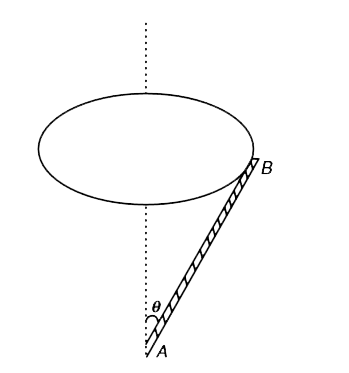
View SolutionA uniform rod of mass m and length L is fixed to an axis, making an angle θ with it as shown in the figure. The rod is rotated about this axis so that the free end of the rod moves with a uniform speed ‘v’. Find the angular momentum of the rod about the axis. Is the angular momentum of the rod about point A constant?
View Solution
Knowledge Check
The co-ordinates of the third vertex C on the x-axis so that A(2,0), B(2+2√3,6) and C form an equilateral triangle is :
A(,4)B(1,5)C(2,3)D(5,1)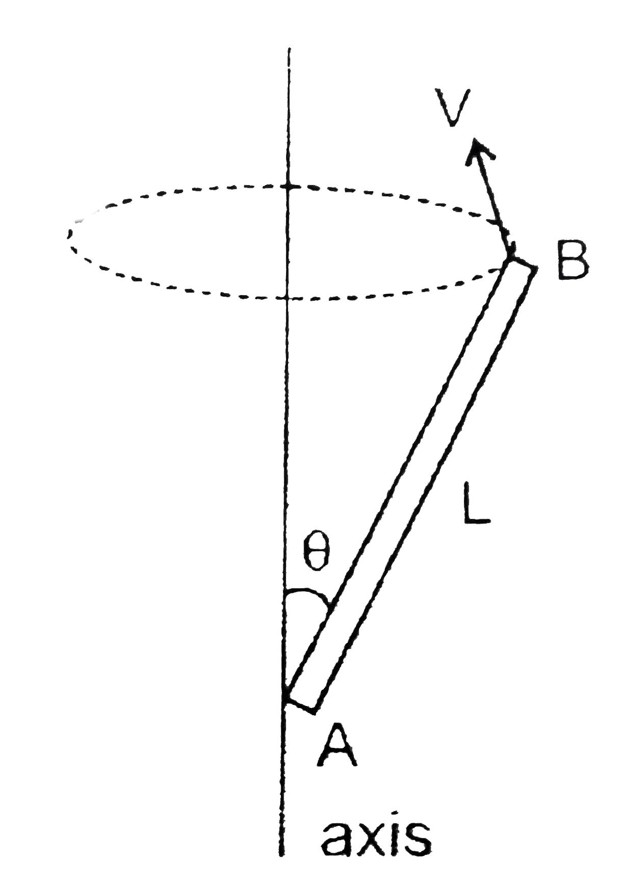
A uniform rod AB of mass m and length L rotates about a fixed vertical axis making a constant angle θ with it as shown in figure. The rod is rotated about this axis, so that point B the free end of the rod moves with a uniform speed V in the horizontal plane then the angular momentum of the rod about the axis is:A12mVLcosθB13mVLsinθCmVLsincosθDzeroTwo straight conducting rails form a right angle where their ends are joined. A conducting bar in contact with the rails starts at the vertex at time t = 0 and moves with constant velocity v along them as shown in Fig. A magnetic field →B is directed into the page. the induced emf in the circuit at any time t is proportional to
 At∘BtCvoltage across L is equal to zero.Dv2
The rod AB oriented parallel to the x′ axis of the reference frame K′ moves in this frame with a velocity v′ along its y′ axis. In its turn, the frame K′ moves with a velocity V relative to the frame K as shown in figure. Find the angle θ between the rod and the x axis in the frame K.

View SolutionA particle of charge q and mass m is moving along the x-axis with a velocity v and enters a region of electric field E and magnetic field B as shown in figures below. For which figure the net force on the charge may be zero?
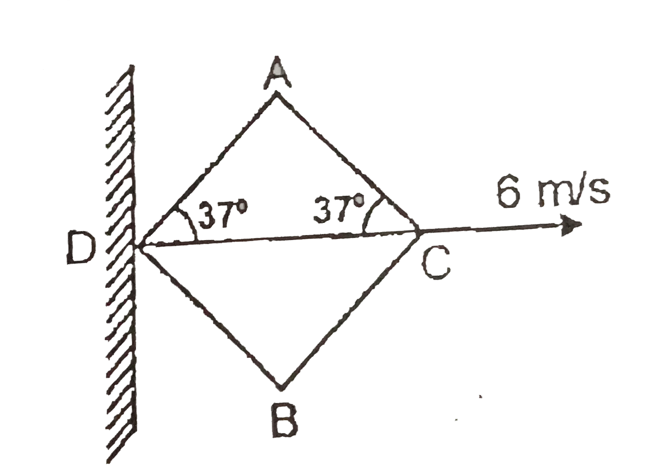
View SolutionA rhombus ABCD is shown in figure. The sides of the rhombus can rotate about vertex A, B, C and D. The vertex C is moving with a velocity of 6 m/s in horizontal direction. Determine the velocity of vertex A
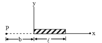
View SolutionA rod of length 'l' is placed along x-axis. One of its ends is at the origin. The rod has a non-uniform charge density λ= a, a being a positive constant. Electric potential at P as shown in the figure is -
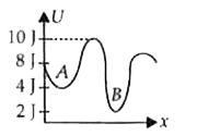
View SolutionA particle moves along x-axis whose potential energy versus x-coordinate graph is shown in the given figure. At x = 0, the particle is released form rest. Two potential wells A and B are shown in the figure. Then,
View Solution
