Various circuits are used to observe the phenomenon of self-induction. Among these are the circuits shownig Figures (a) and (h). III Figure (a), key K is initially opened and the current Ilows through the induction coil L and resistor R connected iu series. In Figure (h), key K is initially closed and the current branches on to RandL. In both circuits the resistance of the coil L is much lower than R. Can an induction emf be generated in either' one of these circuits that is higher than the emf of the DC source?
Step by step video & image solution for Various circuits are used to observe the phenomenon of self-induction. Among these are the circuits shownig Figures (a) and (h). III Figure (a), key K is initially opened and the current Ilows through the induction coil L and resistor R connected iu series. In Figure (h), key K is initially closed and the current branches on to R and L. In both circuits the resistance of the coil L is much lower than R. Can an induction emf be generated in either' one of these circuits that is higher than the emf of the DC source? by Physics experts to help you in doubts & scoring excellent marks in Class 12 exams.
Updated on:21/07/2023Topper's Solved these Questions
Similar Questions
Knowledge Check
In the circuit shown in figure, the capacitors are initially uncharged. The current through resistor PQ just after closing the switch is
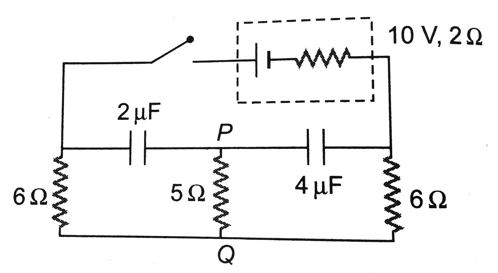 A2A from P to QB2A from Q to PC6A from P to QDzero
The figure shows an L−R circuit the time constant for the circuit is
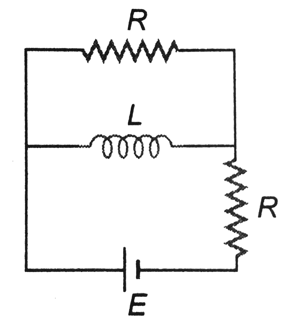 AL2RB2LRC2RLDR2L
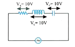
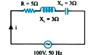
The current in the series L-C-R circuit is
Ai=imsin(ωt+ϕ)Bi=vm√R2+(Xc−XL)2sin(ωt+ϕ)Ci=2imcos(ωt+ϕ)DBoth (a) and (b)
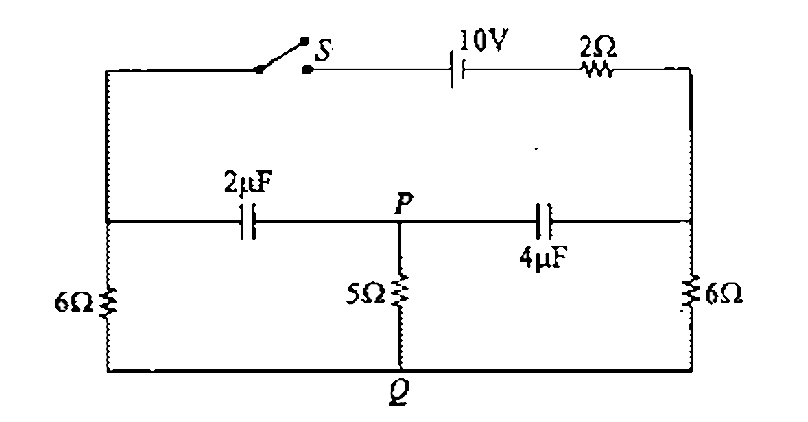
In the circuit shown in figure-3.351 the capacitors are initially uncharged. The current through resistor PQ just after closing the switch is :
View SolutionA series L-C-R circuit is given in figure . The current through the circuit is
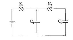
View SolutionIn the circuit shown in Figure, initially key K1 is closed and key K2 is open. Then K1 is opened and K2 is closed. Then
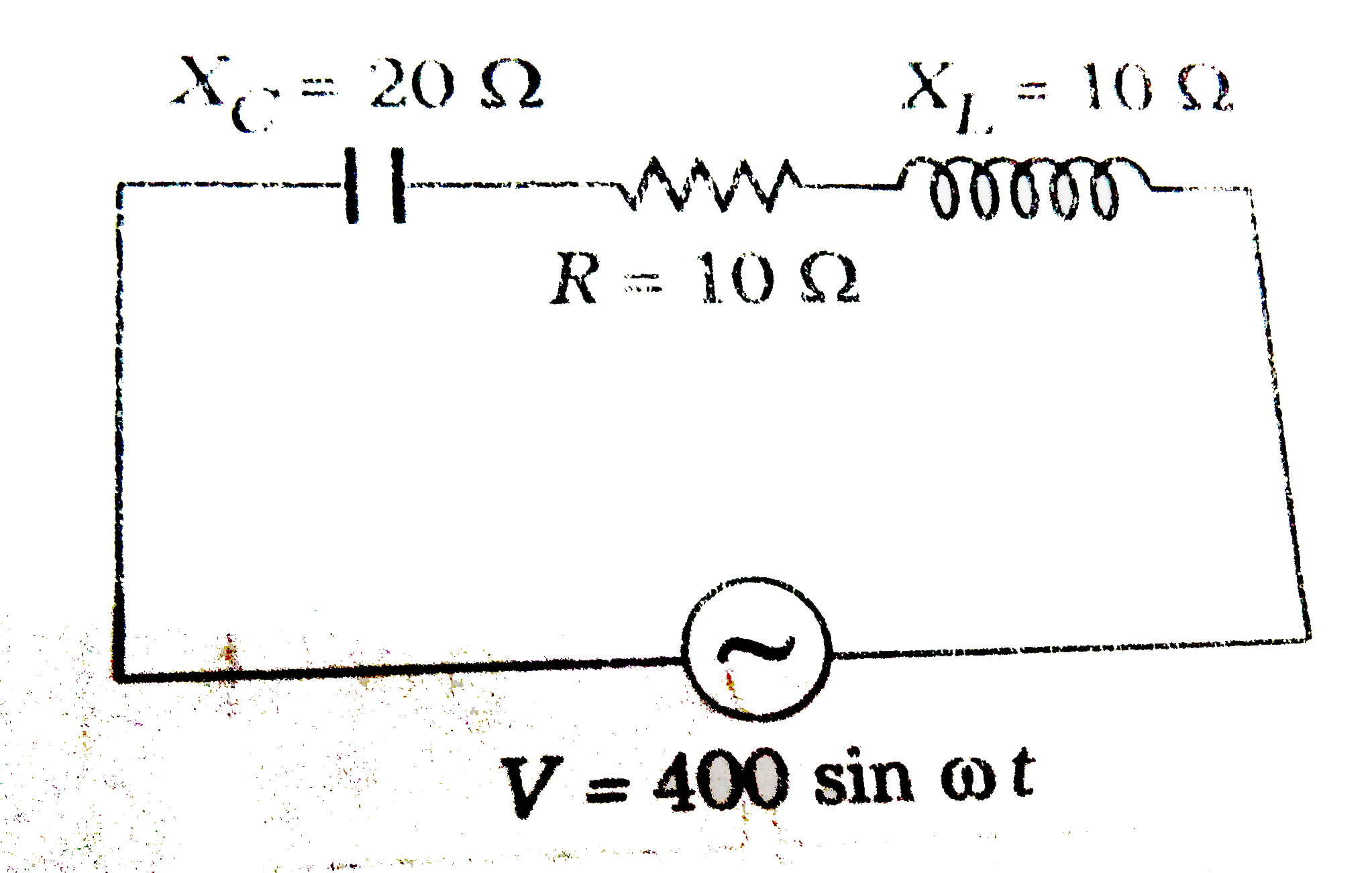
View SolutionIn the L-C-R circuit as shown in figure,
View SolutionIn an AC circuit, a resistance R is connected in series with an inductance L. If the phase angle between the voltage and the current is pi//4 then the value of ihe inductive reactance is
View Solution

