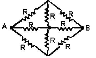
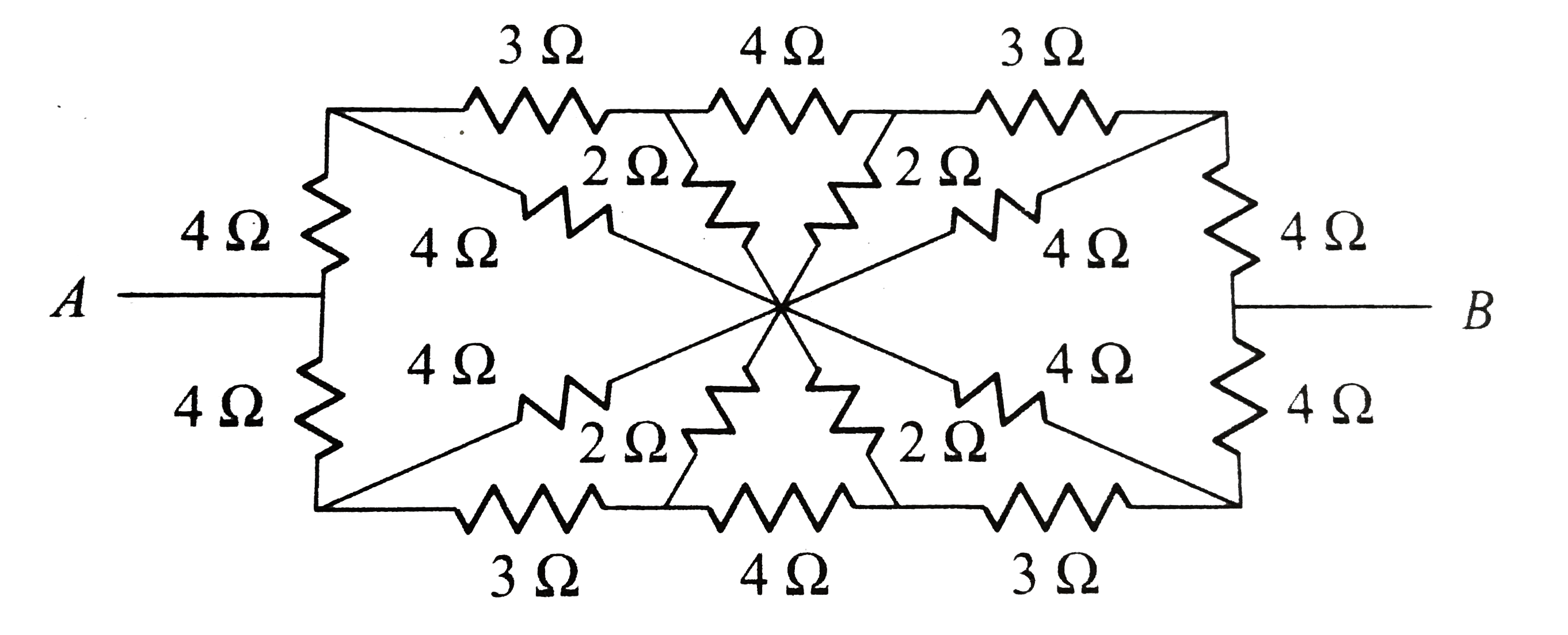
A bridge circuit is shown in figure. The equivalent resistance between A and B will be
A
B
C
D
Video Solution
Text Solution
The correct Answer is:A
|
Answer
Step by step video, text & image solution for A bridge circuit is shown in figure. The equivalent resistance between A and B will be by Physics experts to help you in doubts & scoring excellent marks in Class 12 exams.
Updated on:21/07/2023Topper's Solved these Questions
- CURRENT ELECTRICITYBook:ERRORLESS Chapter:CURRENT ELECTRICITYExercise:Kirchhoff s Law, cells
Explore 8 Videos
- CURRENT ELECTRICITYBook:ERRORLESS Chapter:CURRENT ELECTRICITYExercise:Different Measuring Instruments
Explore 1 Video
- COMMUNICATION SYSTEMBook:ERRORLESS Chapter:COMMUNICATION SYSTEMExercise:S E T
Explore 14 Videos
- ELECTRO MAGNETIC INDUCTIONBook:ERRORLESS Chapter:ELECTRO MAGNETIC INDUCTIONExercise:SET
Explore 20 Videos
Similar Questions
Knowledge Check
Eight resistances each of resistance 5Ω are connected in the circuit as shown in figure. The equivalent resistance between A and B is
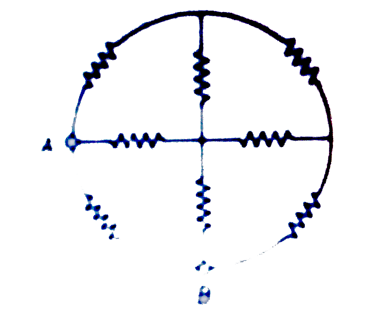 A83ΩB163ΩC157ΩD192Ω
For the circuit shown in fig. the equivalent resistance between A and C is
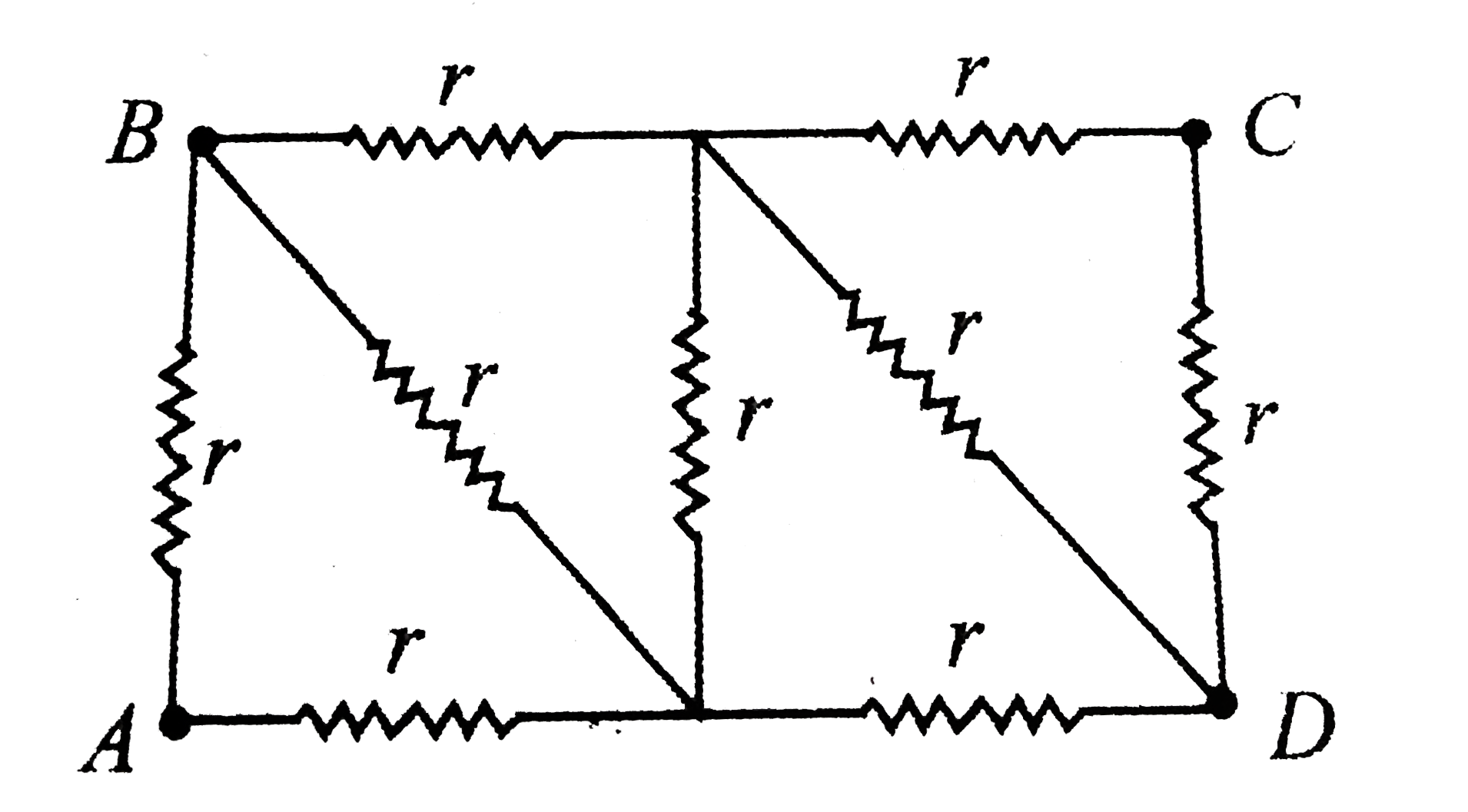 A1211rB1311rC1411rD1511r
Consider the circuit as shown in figure. The equivalent resistance between A and B is
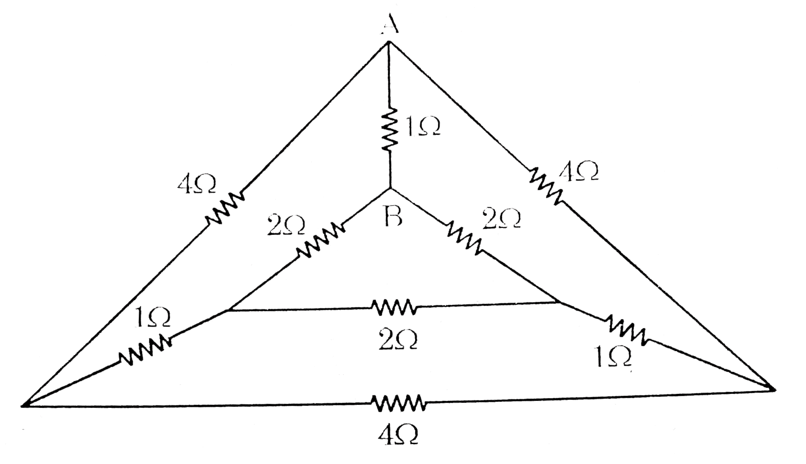 A97ΩB19ΩC79ΩDNone
The equivalent resistance between A and B in the given circuit is:
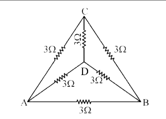
View SolutionThe circuit as shown in figure is equivalent to

View SolutionThe circuit as shown in figure is equivalent to

View SolutionEach resistance of the circuit shown in figure is r. The equivalent resistance between A and B is
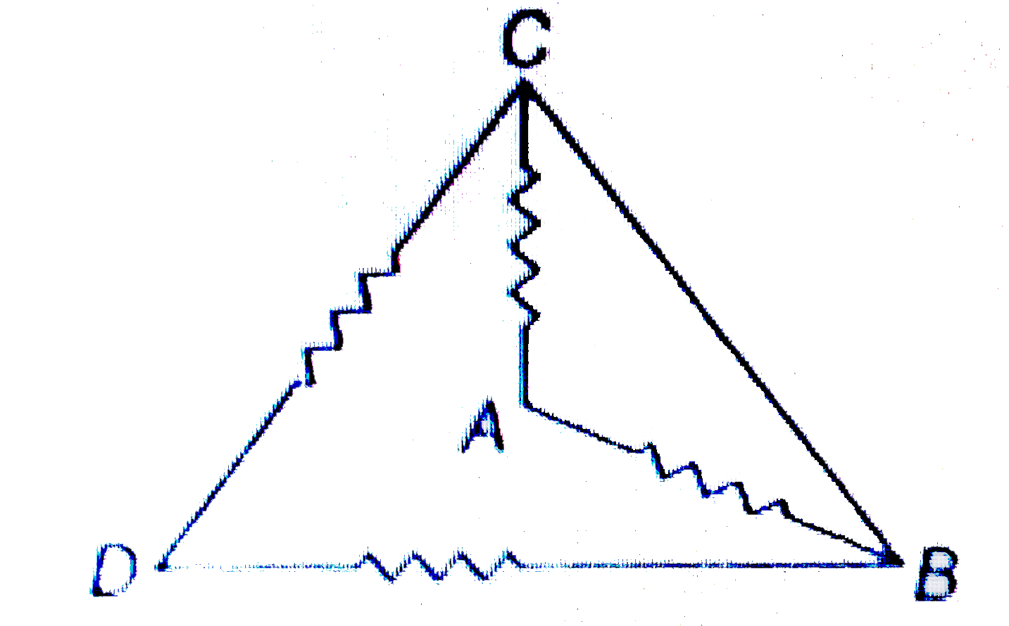
View SolutionA number of resistors are connected as shown in the figure. The equivalent resistance between A and B is
View Solution


