The circuit as shown in figure is equivalent to

A
OR gate
B
NOR gate
C
NAND gate
D
AND gate
Video Solution
Text Solution
The correct Answer is:A
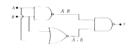
Y¯¯¯¯¯¯¯¯¯¯¯¯¯¯¯¯¯¯¯¯¯¯¯¯¯¯¯¯¯¯¯¯A.B.(¯¯¯¯¯¯¯¯¯¯¯A+B)
=¯¯¯¯¯¯¯¯¯¯¯¯¯¯¯¯¯¯¯¯¯¯¯¯¯¯¯¯(A+B)+¯¯¯¯¯¯¯¯¯¯¯¯¯¯¯¯¯¯¯¯¯¯¯¯¯¯¯¯(A+B) (From De Morgan.s theorem)
=A.B+A+B=A(B+1)+B=A+B
It is the Boolean expression of the OR gate.
|
Topper's Solved these Questions
- ELECTRONIC DEVICESBook:MTG GUIDEChapter:ELECTRONIC DEVICESExercise:CHECK YOUR BEET VITALS
Explore 25 Videos
- ELECTRONIC DEVICESBook:MTG GUIDEChapter:ELECTRONIC DEVICESExercise:AIPMT/NEET (MCQs)
Explore 42 Videos
- ELECTRONIC DEVICESBook:MTG GUIDEChapter:ELECTRONIC DEVICESExercise:AIPMT/NEET (MCQs)
Explore 42 Videos
- ELECTROMAGNETIC WAVESBook:MTG GUIDEChapter:ELECTROMAGNETIC WAVESExercise:AIPMT/NEET(MCQs)
Explore 15 Videos
- ELECTROSTATICSBook:MTG GUIDEChapter:ELECTROSTATICSExercise:AIPMT/NEET (MCQ.s)
Explore 34 Videos
Similar Questions
Knowledge Check
The circuit as shown in the figure is equivalent to
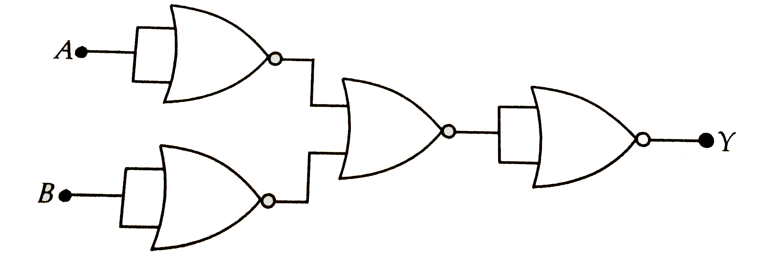 AAND gateBNOT gateCOR gateDNAND gate
The circuit as shown in the figure is equivalent to
 AAND gateBNOR gateCOR gateDNAND gate
In the circuit shown in figure
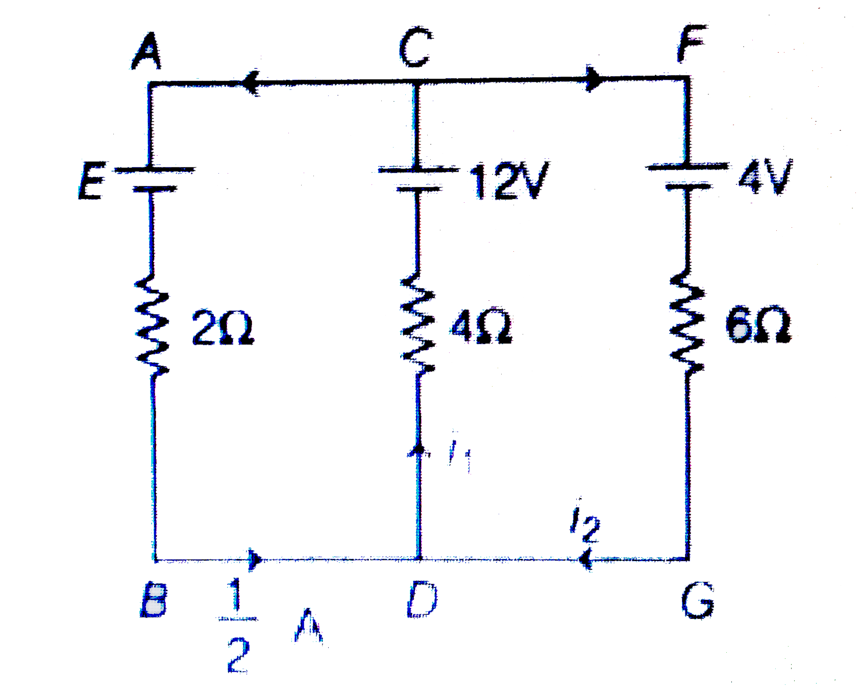 AE = 6.6 VBi1=1.1ACi2=0.5ADE = 4.4 V
The situation shown in figure is equivalent to
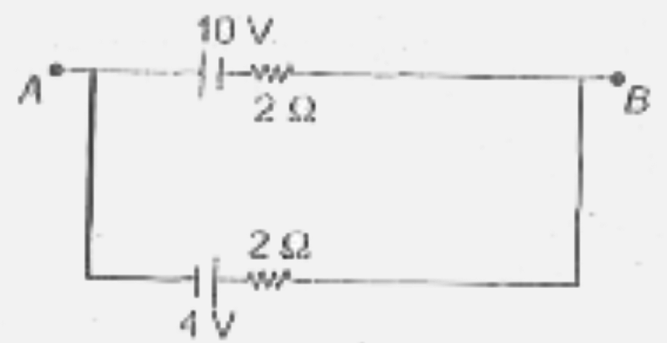
View SolutionIn the circuit shown in figure
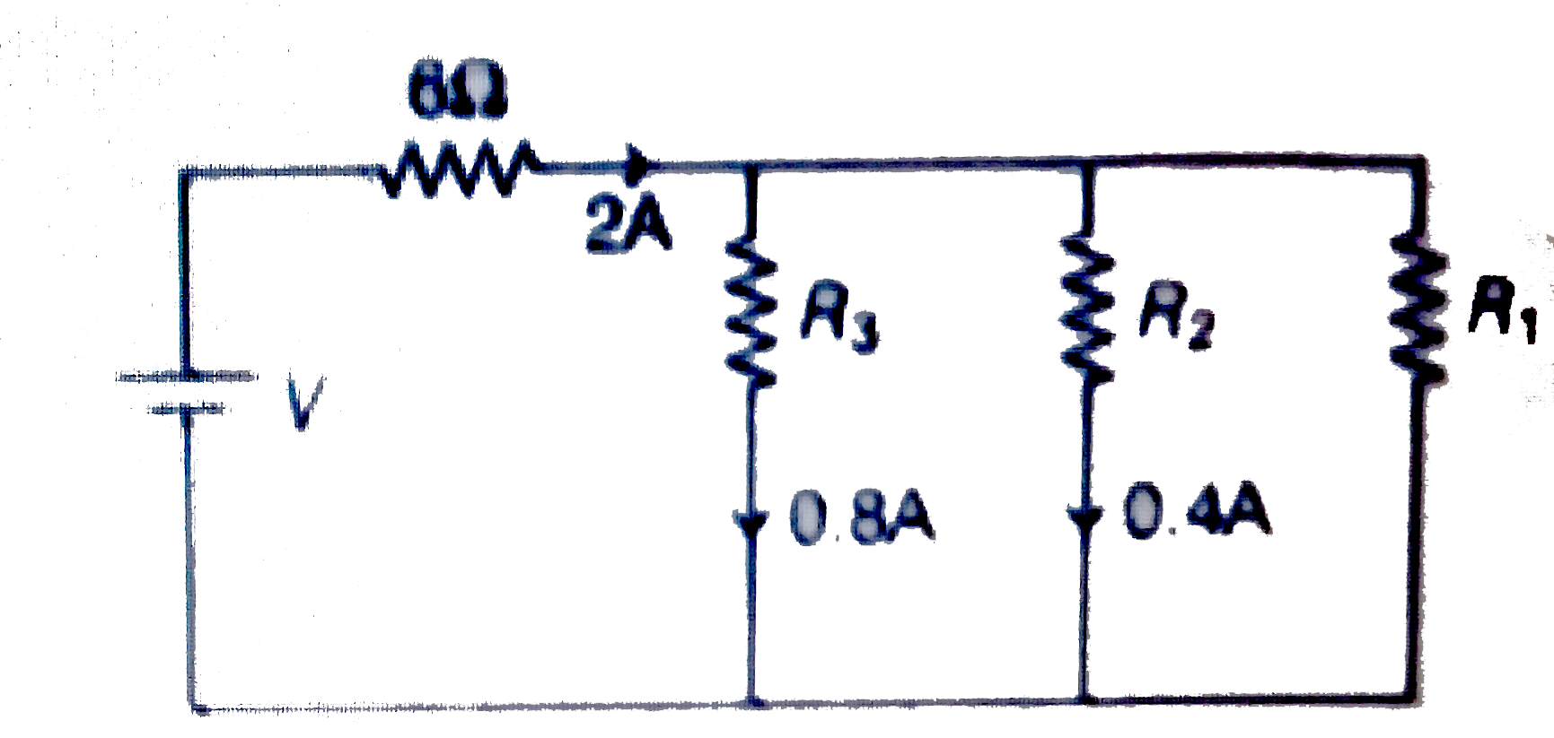
View SolutionIn the circuit shown in figure
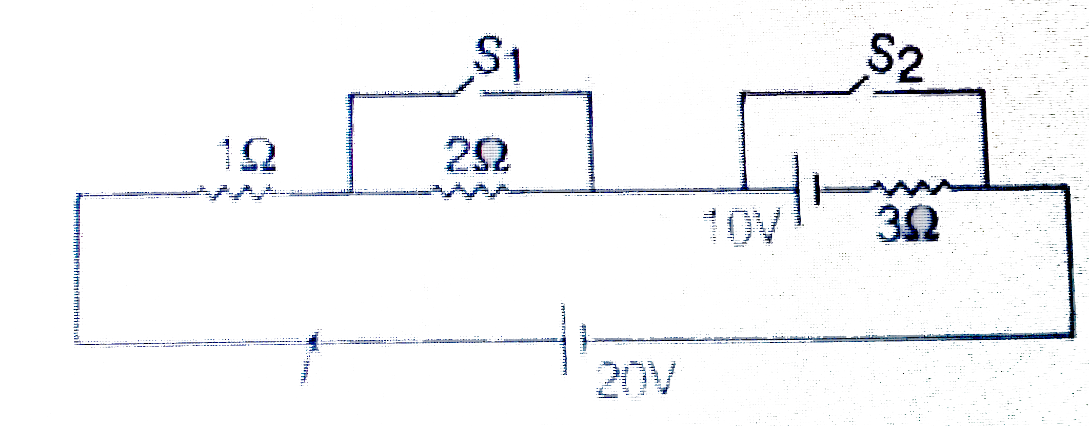
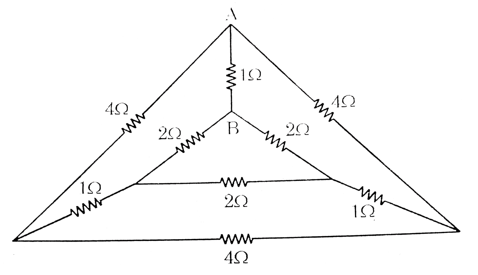
View SolutionConsider the circuit as shown in figure. The equivalent resistance between A and B is
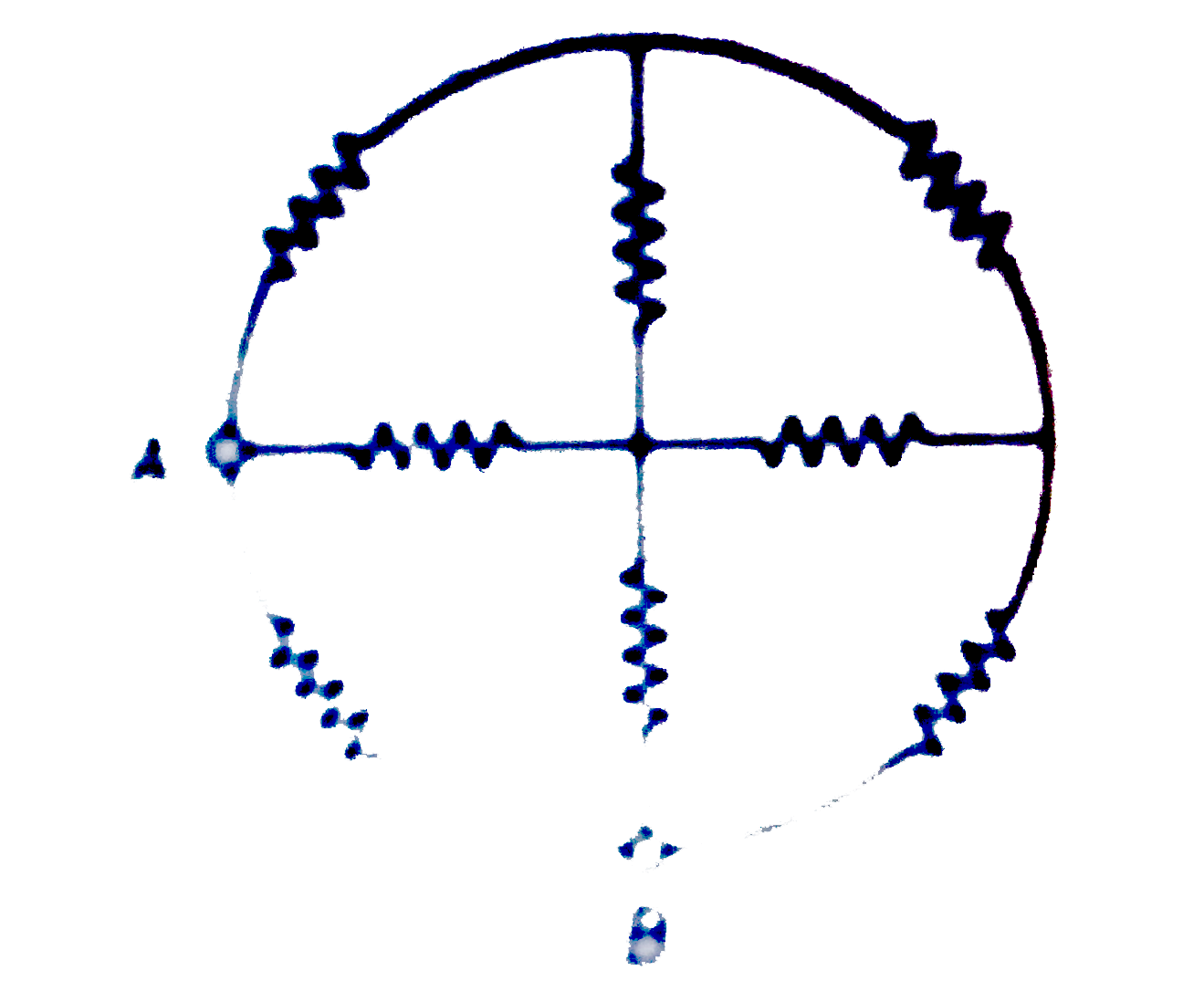
View SolutionEight resistances each of resistance 5Ω are connected in the circuit as shown in figure. The equivalent resistance between A and B is
View Solution


