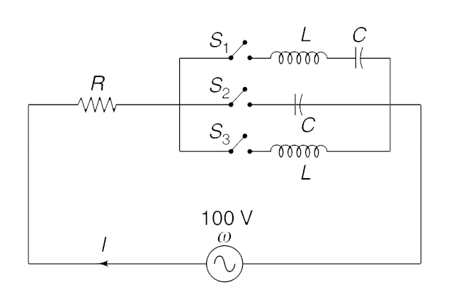
In the circuit shown in the figure, one of the three switches is kept closed and other two are open. The value of resistance is R = 20 Ω. When the angular frequency(w) of the 100 V source is adjusted to 500 rad/s, 1000 rad/s and 2000 rad/s it was found that the current I was 4A, 5A and 4A respectively.
(a) Which switch id closed ?(S1,S2orS3)
(b)Find the value of L and C.
The correct Answer is:(a)S1(b)L=100mH,C=100μF
Step by step video, text & image solution for In the circuit shown in the figure, one of the three switches is kept closed and other two are open. The value of resistance is R = 20 Omega. When the angular frequency(w) of the 100 V source is adjusted to 500 rad/s, 1000 rad/s and 2000 rad/s it was found that the current I was 4A, 5A and 4A respectively. (a) Which switch id closed ?(S_(1),S_(2) "or" S_(3)) (b)Find the value of L and C. by Physics experts to help you in doubts & scoring excellent marks in Class 12 exams.
Updated on:21/07/2023Topper's Solved these Questions
Similar Questions
Knowledge Check
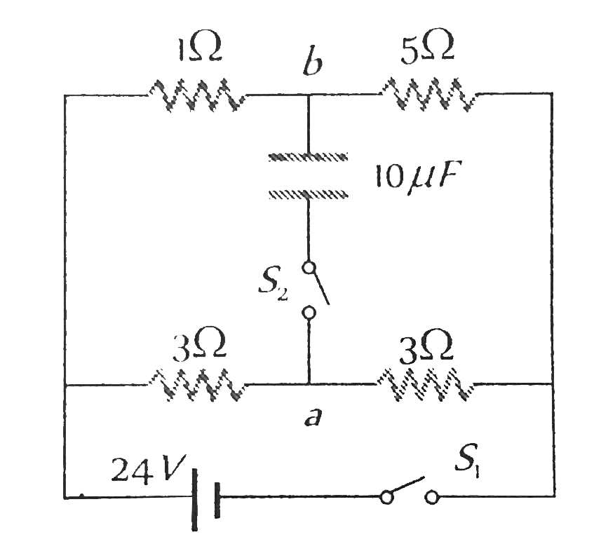
In the circuit shown in figure, switch S is initially closed and S is open. Find V-V
 A4VB8VC12VD16V
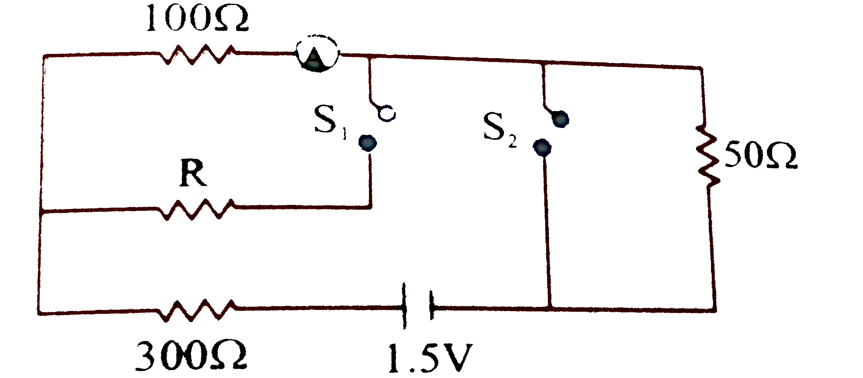
In the given ciruit Ammeter reading is same when both switches S1,S2 are closed or opened. The value of resistance R isA200ΩB100ΩC400ΩD−300ΩIn the circuit shown, the reading of ammeter when switch S is open and when switch S is closed respectively are
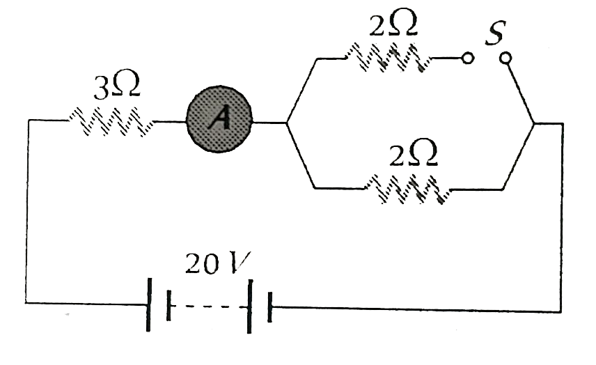 A3A and 4AB4A and 5AC5A and 6AD6A and 7A
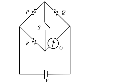
In the circuit P≠R, the reading of the galvanometer is same with switch S open or closed. Then
View Solution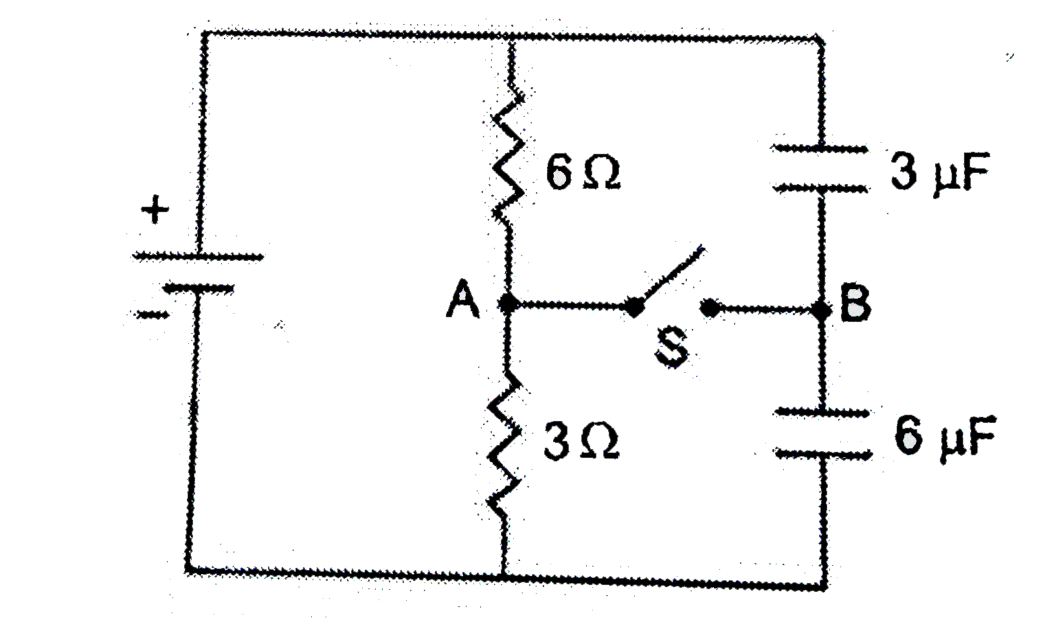
In the circuit shown above, when then switch S is closed,
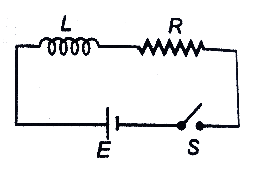
View SolutionIn the circuit shown in figure L=10H,R=5Ω,E=15V. The switch S is closed at t=0. At t=2s the current in the circuit is
View SolutionIn the circuit shown in figure switch S is closed at time t=0
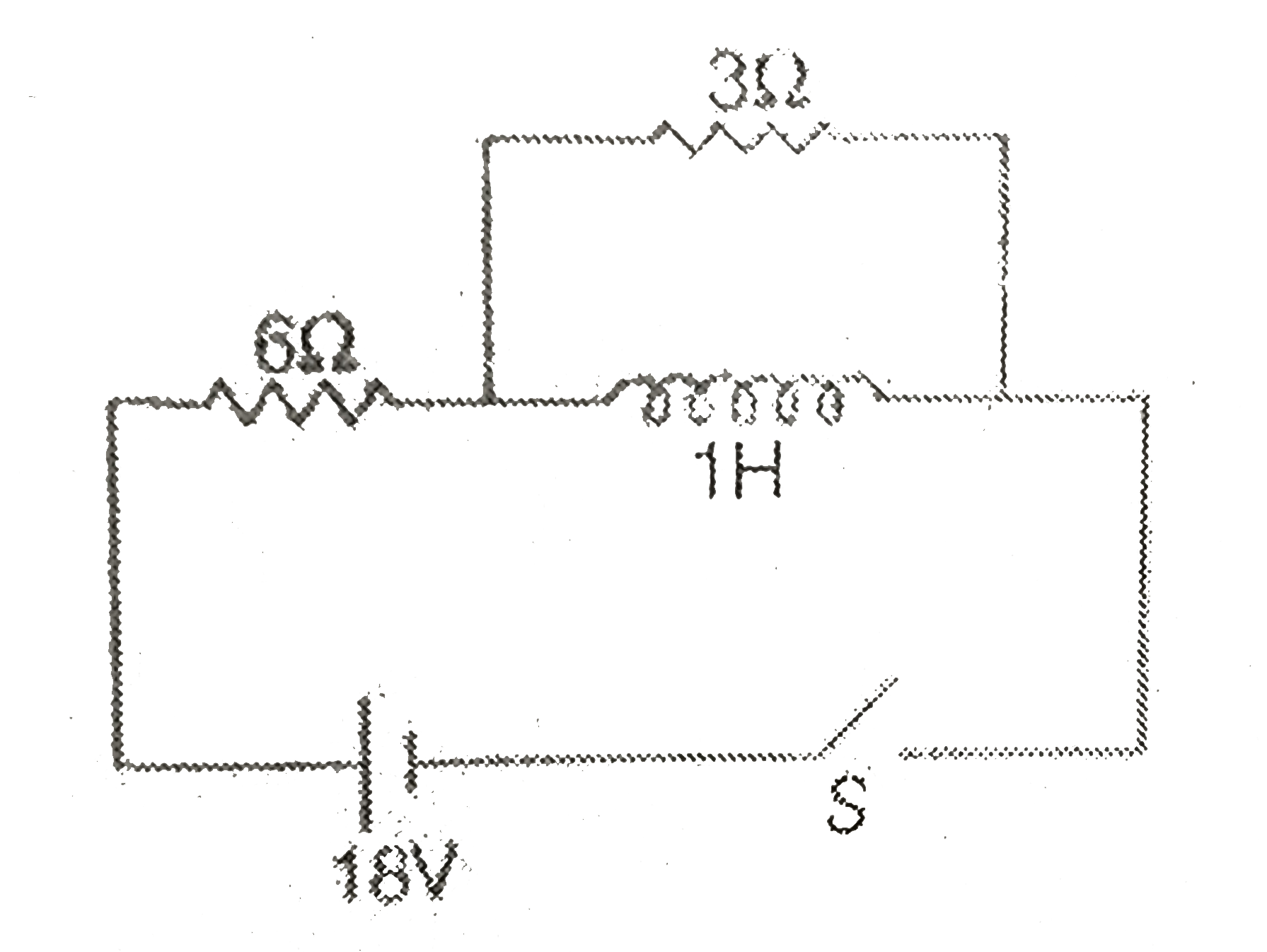
At what time current through 3Ω resistance and 1H inductor are equal?
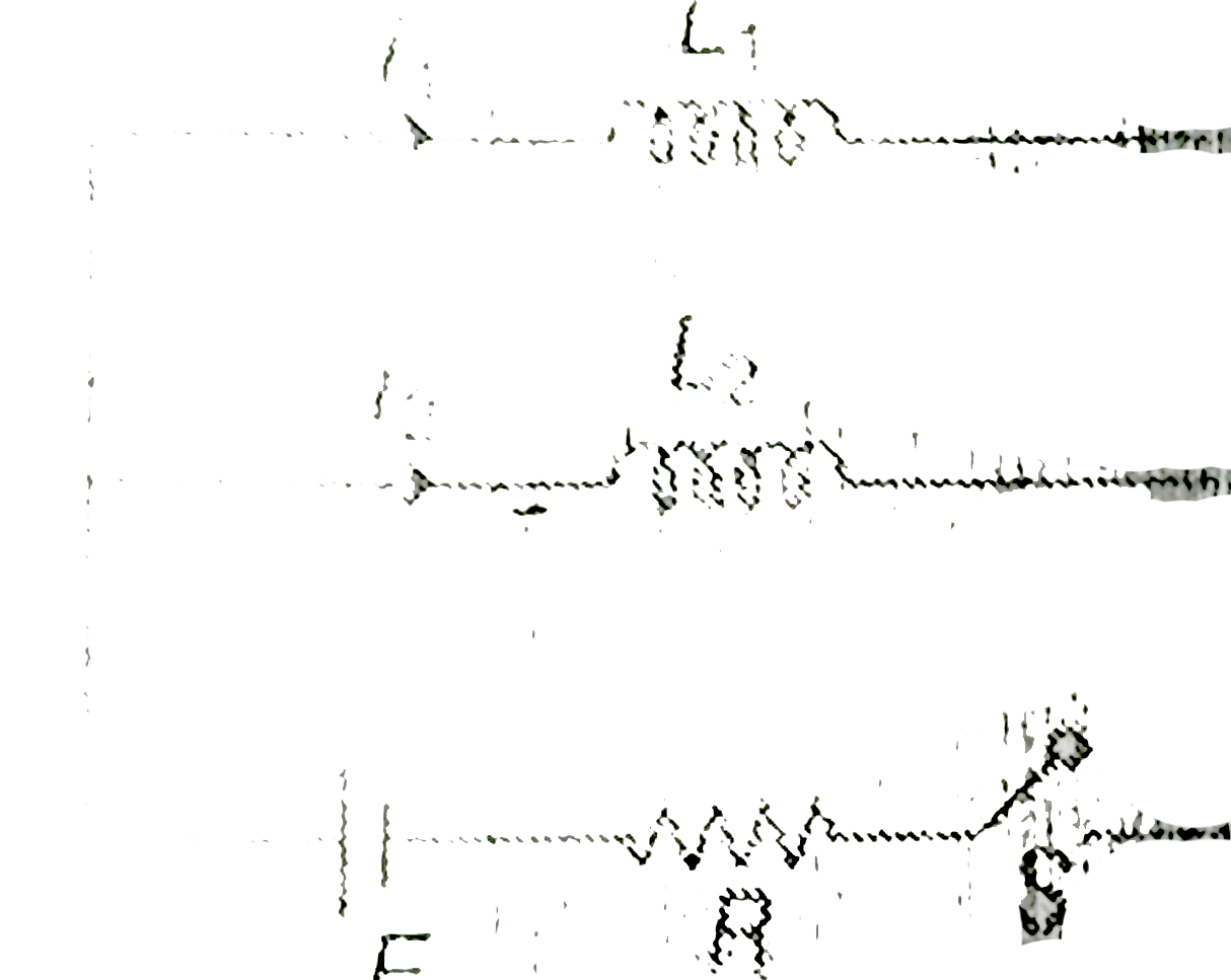
View SolutionIn the circuit shown in the figure The steady state currents i1andi2 in the coils after the switch S is closed are
View Solution


