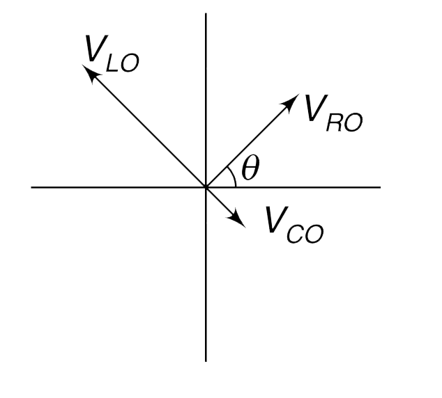
In a series LCR circuit the phasors corresponding to voltage across resistance, capacitor and inductor at an instant are as shown in the Figure and have amplitudes ofVRO=4volt,VCO=3volt,andVLO=6volt
(a) Is the source frequency larger than or lesser than the resonance frequency? Does the current (I) lead or lag the source voltage?
(b) Find the voltage amplitude of the source.
(c) If VR phasor makes θ=53∘ at time t = 0, write the source voltage as function of time. Take angular frequency of the source to be ω[sin53∘=45]

The correct Answer is:(a) Source frequency is greater than resonant frequency. Current lags.
(b) 5 volt
(c )V0cosωt
Step by step video, text & image solution for In a series LCR circuit the phasors corresponding to voltage across resistance, capacitor and inductor at an instant are as shown in the Figure and have amplitudes of V_(RO) = 4 "volt", V_(CO) = 3 "volt", and V_(LO) = 6 "volt" (a) Is the source frequency larger than or lesser than the resonance frequency? Does the current (I) lead or lag the source voltage? (b) Find the voltage amplitude of the source. (c) If VR phasor makes theta=53^(@) at time t = 0, write the source voltage as function of time. Take angular frequency of the source to be omega[sin53^(@)=(4)/(5)] by Physics experts to help you in doubts & scoring excellent marks in Class 12 exams.
Updated on:21/07/2023Topper's Solved these Questions
Similar Questions
Knowledge Check
In series LCR circuit voltage drop across resistance is 8V, across inductor is 6V and across capacitor is 12V. Then
Avoltage of the source will be leading current in the circuitBvoltage drop across each element will be less than the applied voltage.Cpower factor of circuit will be 4/3Dnone of these.In a series LCR circuit the rms voltage across the inductance , capacitance and resistance are respectively 4 V, 8 V and 5 V . The RMS voltage of the AC source in the circuit is
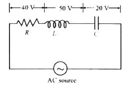
A17 VB13 VC5 VD6.4 VIn series LCR circuit, the voltages across R, L and C shown in figure. The voltage of applied source is
 A110 voltB10 voltC50 voltD70 volt
In a series LCR alternating current circuit under resonancecondition voltage across is exactly equal to the volt age across ……………
View SolutionIn series LCR circuit R=120Ω and it has resonant frequency 4000rad/sec. At resonance, the voltage across resistance and inductance is 60 V and 40 V respectively. Find the value of L and C in circuit.
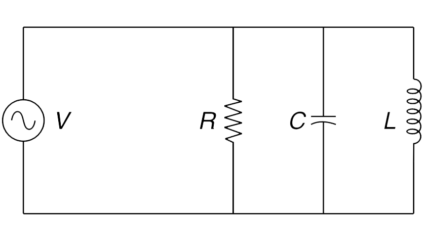
View SolutionIn the circuit shown the source voltage is given asv=V0 sin ωt. Find the current through the source as a function of time.

View SolutionIn LCR series circuit source voltage is 120 volt and voltage in inductor 50 volt and resistance is 40 volt then determine voltage in capacitor.
View SolutionIn a series LR circuit, the voltage drop across inductor is 8 volt and across resistor is 6 volt. Then voltage applied and power factor of circuit respectively are:
View Solution
