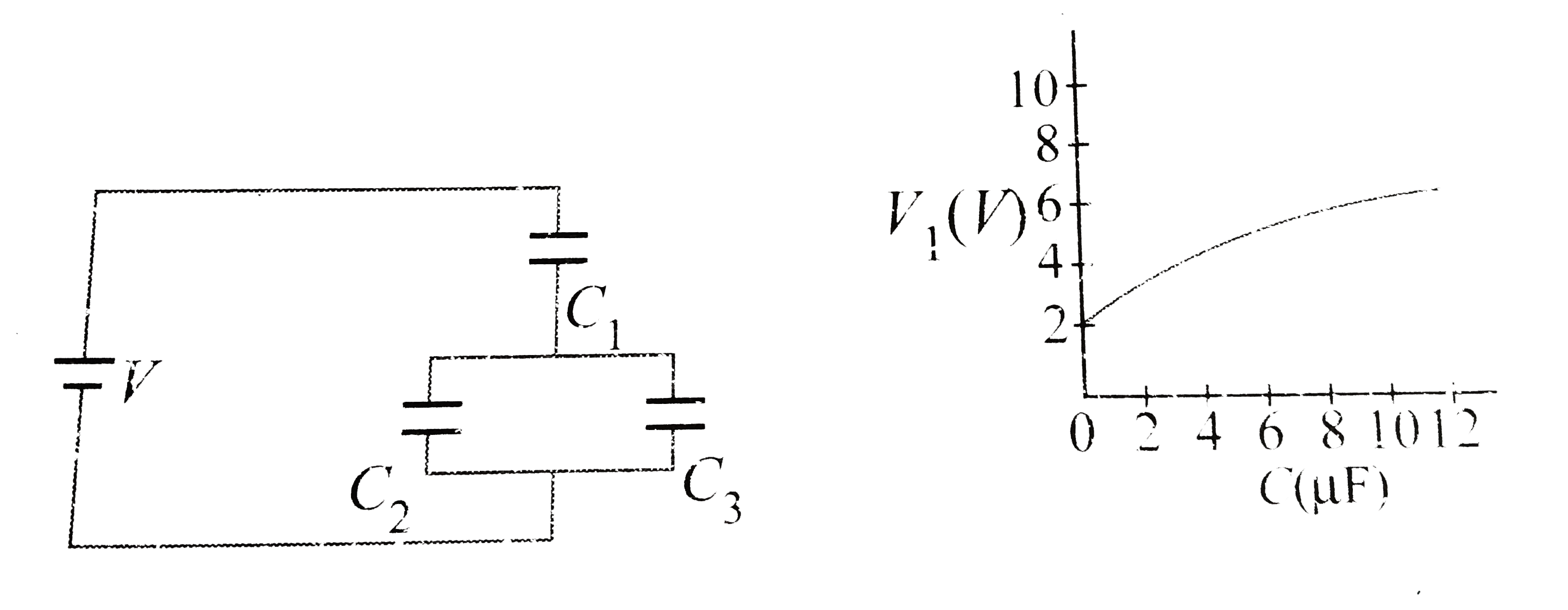
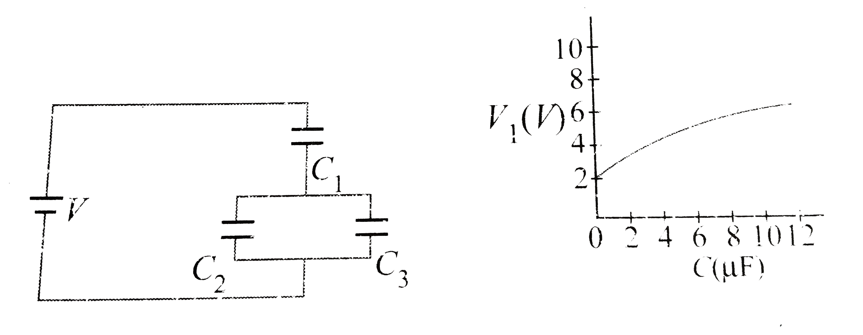
Capacitor C3 in the circuit is variable capacitor (its capacitance can be varied). Graph is plotted between potential difference V1 (across capacitor C1) versus C3.
Electric potential V1 approaches on asymptote of 10 volts as C3→∞
0The value of C3 for which potential difference across C1 will become 8V, is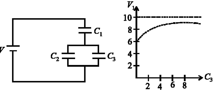
1.5C1
2.5C1
3.5C1
4.5C1
Step by step video & image solution for Capacitor C_(3) in the circuit is variable capacitor (its capacitance can be varied). Graph is plotted between potential difference V_(1) (across capacitor C_(1)) versus C_(3). Electric potential V_(1) approaches on asymptote of 10 volts as C_(3) to infty 0The value of C3 for which potential difference across C_(1) will become 8V, is by Physics experts to help you in doubts & scoring excellent marks in Class 12 exams.
Updated on:21/07/2023Topper's Solved these Questions
Similar Questions
Capacitor C3 in the circuit is variable capacitor (its capacitance can be varied). Graph is plotted between potential difference V1 (across capacitor C1) versus C3.
Electric potential V1 approaches on asymptote of 10 volts as C3→∞
The ratio of the capacitance C1C2 will be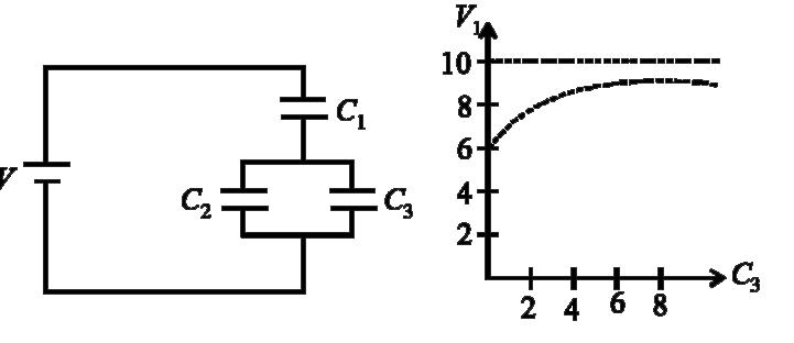
View SolutionCapacitor C3 in the circuit is variable capacitor (its capacitance can be varied). Graph is plotted between potential difference V1 (across capacitor C1) versus C3.
Electric potential V1 approaches on asymptote of 10 volts as C3→∞
The ratio of energy stored in capacitorC1 to that of total energy whenC3→∞ is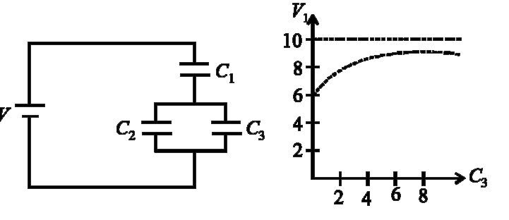
View Solution
Knowledge Check
Capacitor C3 in the circuit is a veriable capacitor (its capacitance can be varied). Group is plotted between potential difference V1 (across capacitor C1) versus C3. Electric potential V1 approaches to 10 V as C3→∞. Given that C1+C2=10μF

EMF of the battery is equal toA10 VB12 VC16 VD20 VCapacitor C3 in the circuit is a variable capacitor (its capacitance can be varied). C1andC2 are of fixed values. Graph is plotted between potential difference V1 (across capacitor C1) versus C3. Electric potential V1 approches on asymptote of 10 V as C3∝∞.
 ,
,
The electric potential V across the battery is equal toA10VB12VC16VD20VCapacitor C3 in the circuit is a variable capacitor (its capacitance can be varied). C1andC2 are of fixed values. Graph is plotted between potential difference V1 (across capacitor C1) versus C3. Electric potential V1 approches on asymptote of 10 V as C3∝∞.
 ,
,
When V1=4Vm then C3 is equal toA5C2/2B5C1/3C5C2/3Dnone of these
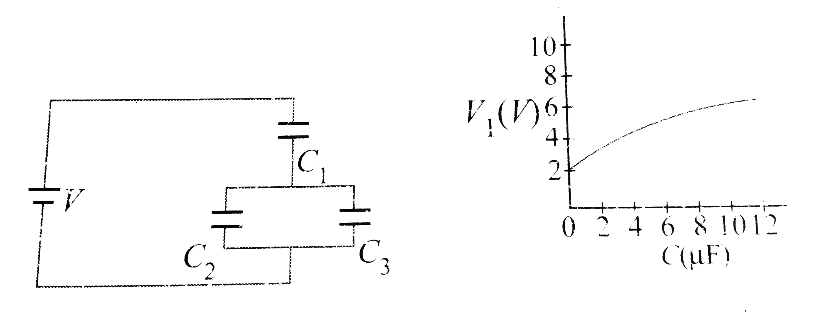
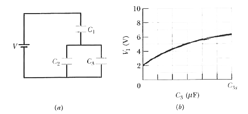
Capacitor 3 in Fig. 25-40a is a variable capacitor (its capacitance C3 can be varied) Figure 25-40b gives the electric potential V1 across capacitor 1 versus C3 The horizontal scale is set by C3s=12.0μF Electric potential V1 approaches as asymptote of 8.0 V as C3→∞ What are (a) the electric potential V across the battery , (b) C1 and (c) C2?
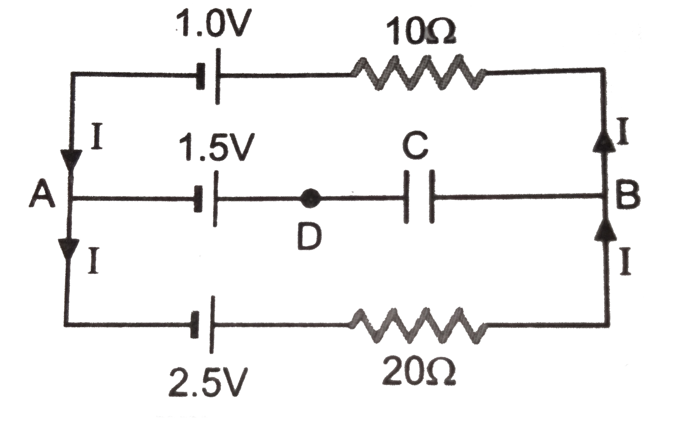
View SolutionIn the circuit diagram find the potential difference across the plates of capacitor C
View SolutionIn the circuit shown the capacitors are C1=15μF,C2=10μFandC3=25μF. Find
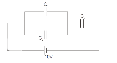
the potential difference across each capacitor.
View SolutionCapacitor C3 in the circuit is a veriable capacitor (its capacitance can be varied). Group is plotted between potential difference V1 (across capacitor C1) versus C3. Electric potential V1 approaches to 10 V as C3→∞. Given that C1+C2=10μF

The capacitance of the capacitor C1 value
View SolutionCapacitor C3 in the circuit is a variable capacitor (its capacitance can be varied). C1andC2 are of fixed values. Graph is plotted between potential difference V1 (across capacitor C1) versus C3. Electric potential V1 approches on asymptote of 10 V as C3∝∞.
 ,
,
Relation between C1andC2 is
View Solution
