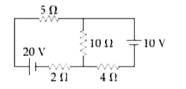
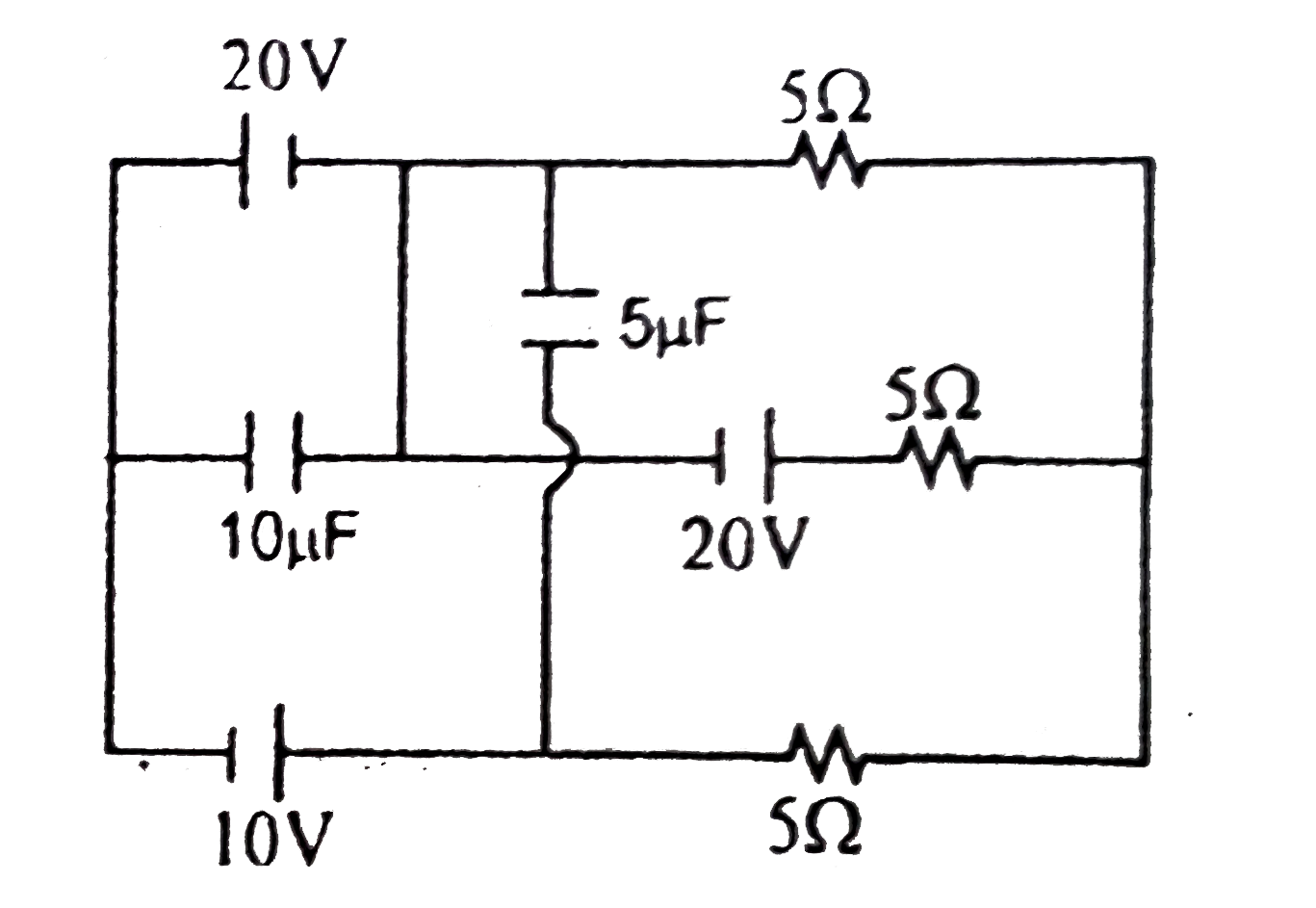
In the figure shown : (All batteries are ideal)
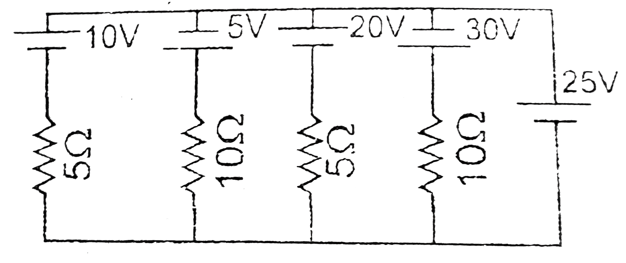
current through 25 V cell is 20 A
current through 25 V cell is 12.5 A
power supplied by 20 V cell is 20 W
power supplied by 20 V cell is -20 W
The correct Answer is:B, D
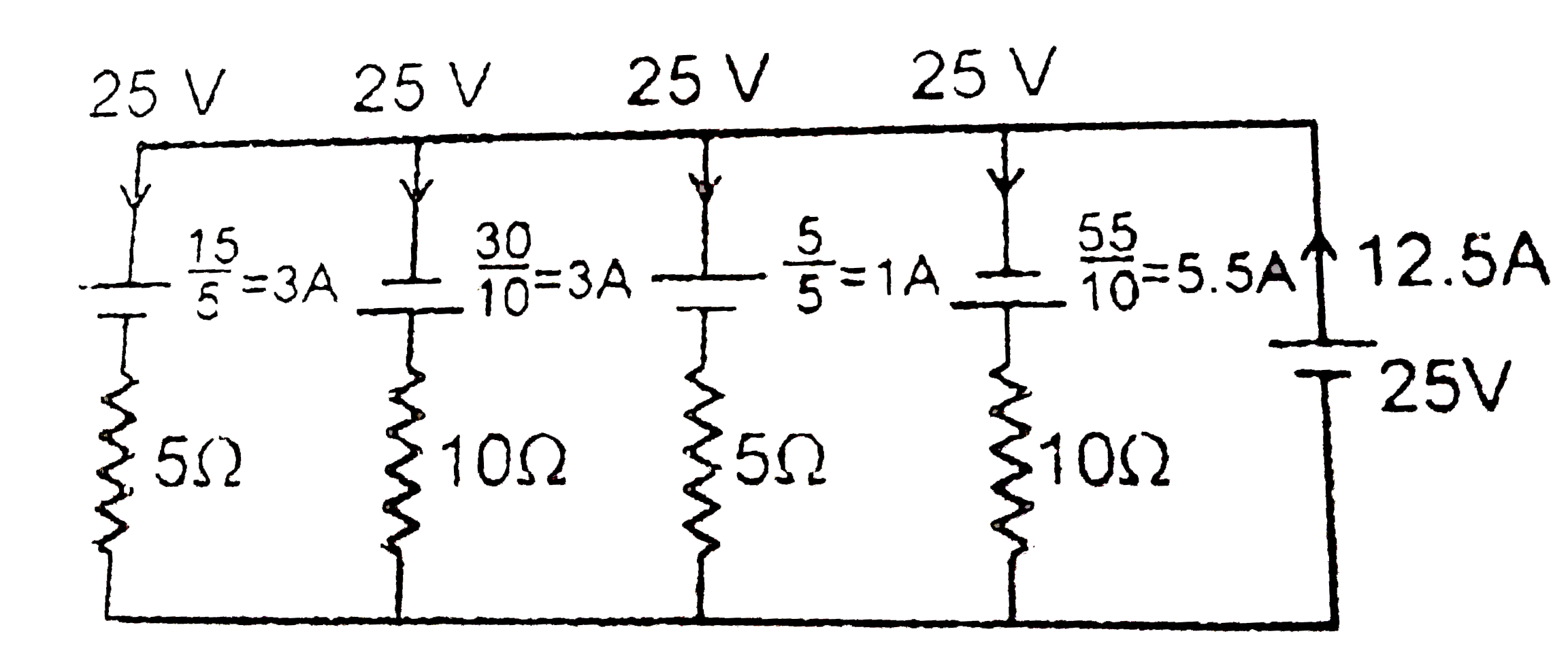
Power supplied by 20 V cell =(−1)(20)=−20W
(as the cell is not supplying the power, it is eating the power (getting charged)
Topper's Solved these Questions
- DAILY PRACTICE PROBLEMBook:RESONANCEChapter:DAILY PRACTICE PROBLEMExercise:DPP No.38
Explore 20 Videos
- DAILY PRACTICE PROBLEMBook:RESONANCEChapter:DAILY PRACTICE PROBLEMExercise:DPP No.39
Explore 9 Videos
- DAILY PRACTICE PROBLEMBook:RESONANCEChapter:DAILY PRACTICE PROBLEMExercise:DPP No.36
Explore 20 Videos
- CURRENT ELECTRICITYBook:RESONANCEChapter:CURRENT ELECTRICITYExercise:High Level Problems (HIP)
Explore 21 Videos
- ELECTRO MAGNETIC WAVESBook:RESONANCEChapter:ELECTRO MAGNETIC WAVESExercise:Exercise 3
Explore 27 Videos
Similar Questions
Knowledge Check
In the figure shown all pulleys are ideal and small. The central pulleys is 2 m away from both ends. What is the length (in m) of the string ? The system is in equilibrium
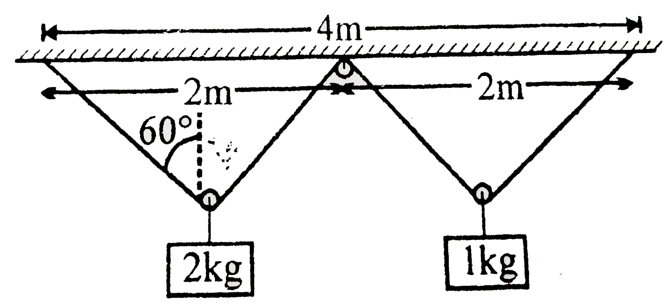 A8√3B4√4[1+2√5]C4√3[1+2√3]D2√3+4
In the circuit shown in the adjacent figure, the batteries are ideal. The charge on the capacitor C is
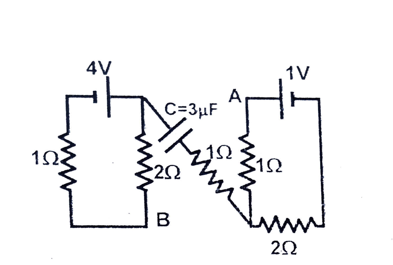 A10μCB20μCC30μCDzeo
Assertion : In the circuit shown in figure, battery is ideal. If a resistance R0 is cannected in parallel with R, then power across R will increase.
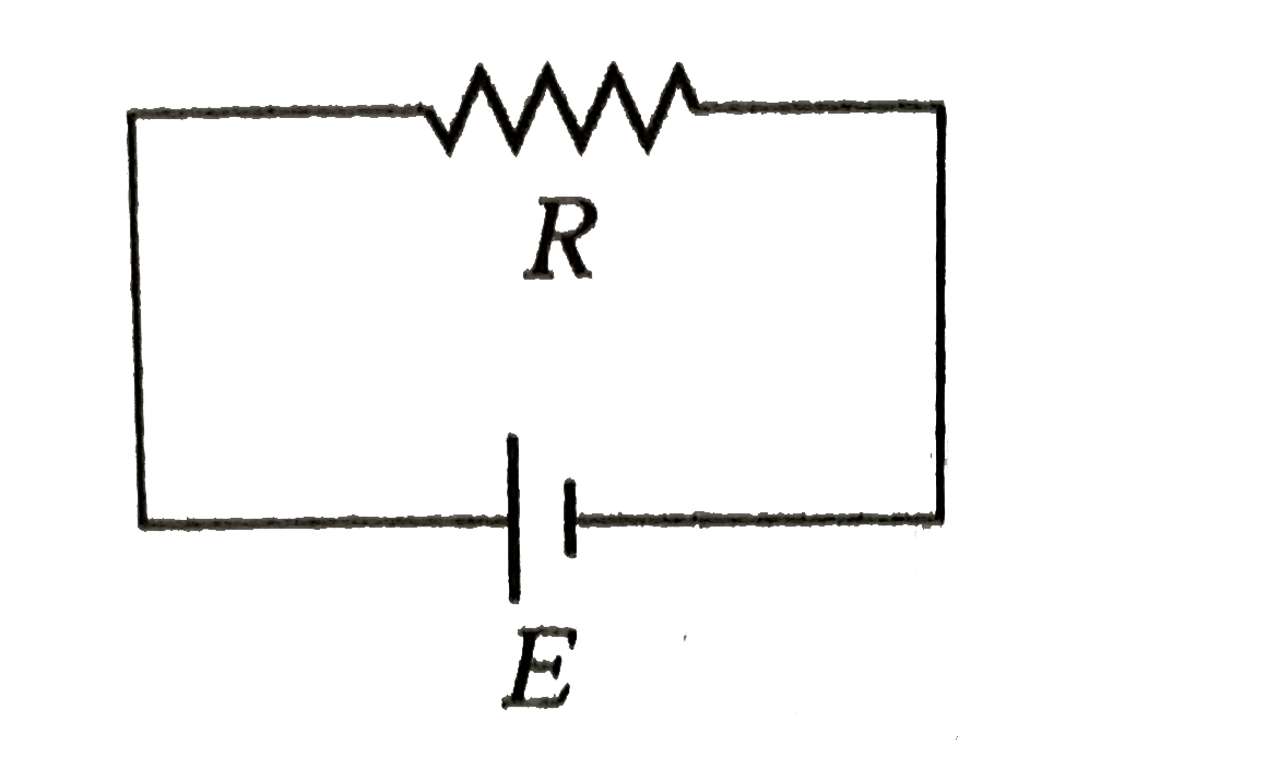
Reason : Current drawn from the battery will increase.AIf both Assertion and Reason are true and Reason is the correct explanation of Assertion.BIf both Assertion and Reason are true and Reason is not correct explanation of Assertion.CIf Assertion is true but Reason is false.DIf Assertion is false but Reason is true.
in the figure shown , a circuit contains two identical resistors with resistance R=Ω and an inductance with L=2 H ,An ideal battery of 15 V is connected in the circuit what will be the current through the battery long after the switch is clossed ?
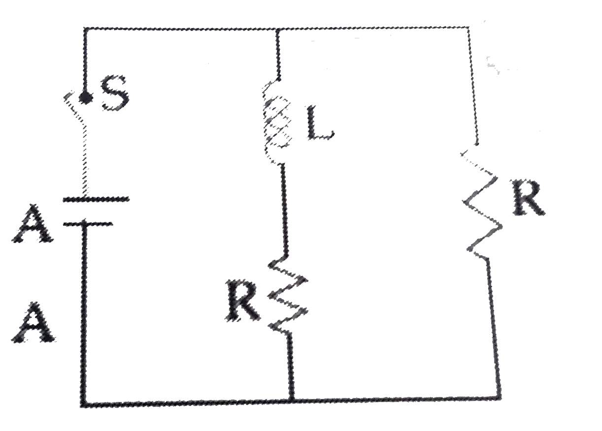
View SolutionFind the ratio of charges on 5μF and 10μF capacitor when circuit is in steady state. All the batteries are ideal.
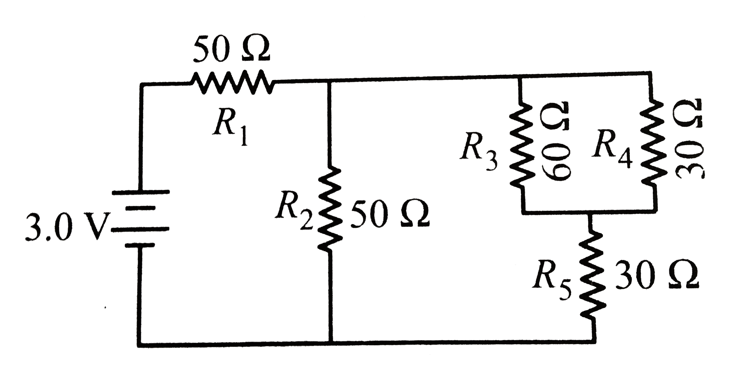
View SolutionIn the circuit shown, the resistances are given in ohms and the battery is assumed ideal with emf equal to 3.0 V.
View SolutionIn the process shown in the figure on an ideal diatomic gas, the value of q and ΔH respectively is :

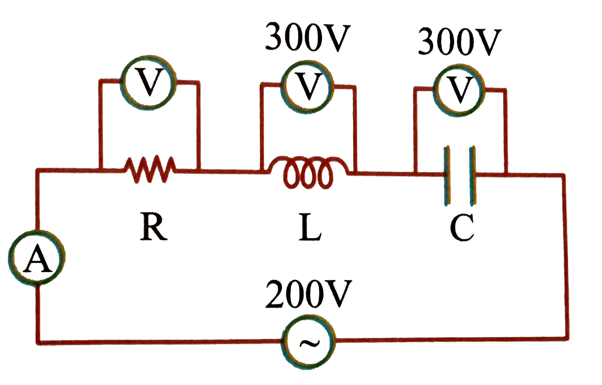
View SolutionIn the series circuit shown in the figure the voltmeter reading will be (all the meters are ideal).
View Solution


