In the circuit diagram shown, intially there is no energy in the inductor and the capacitor. The switch is closed at t=0 . Find the current I as a function of time t .
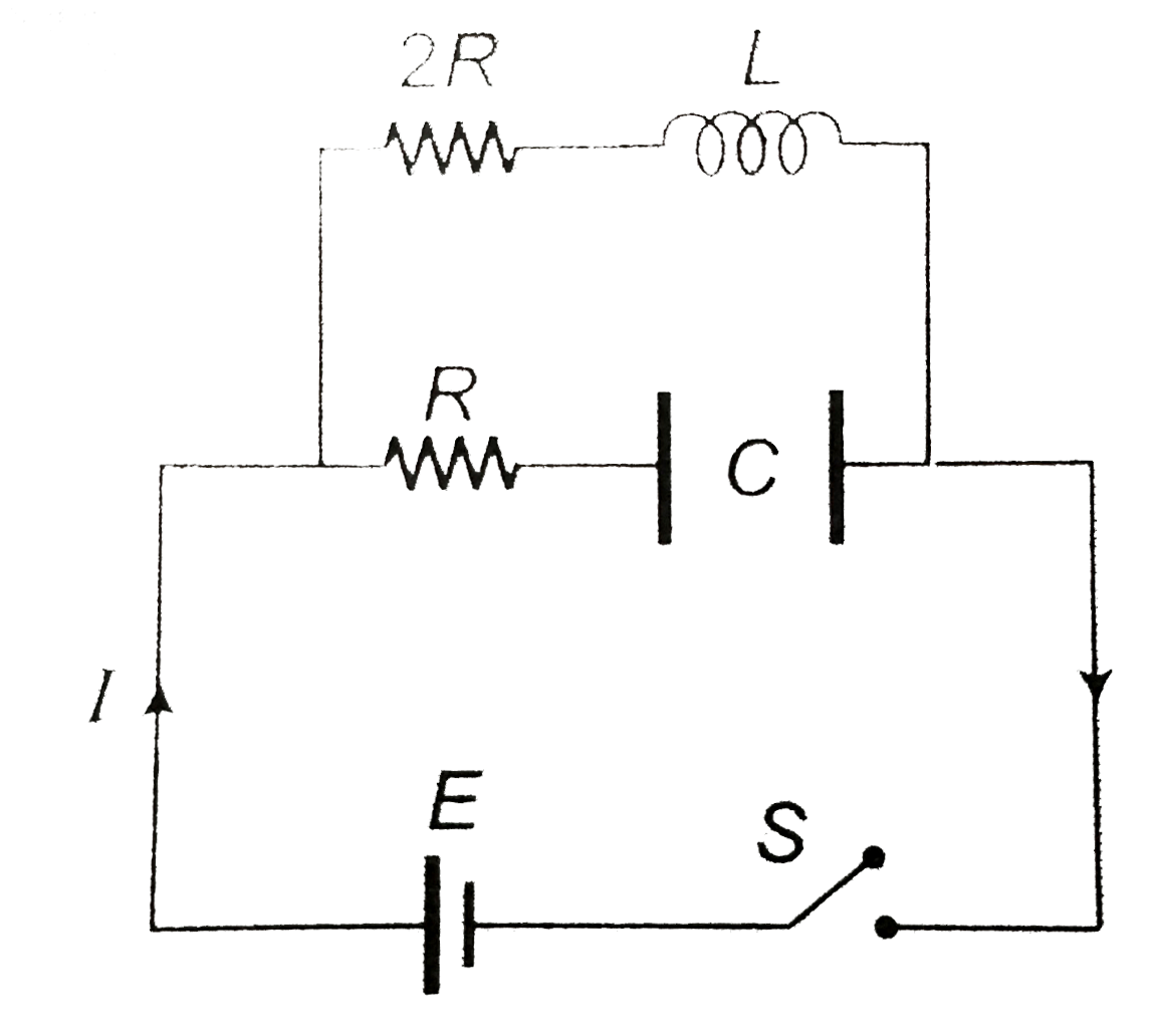
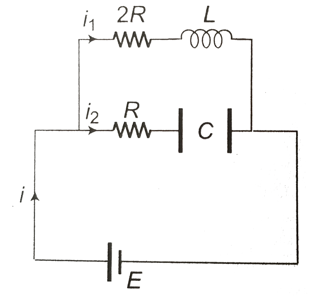
At any time t
i1=E2R(1−e−2RtL)
Change on capacitor
q=CE(1−e−t/RC)
i2=dqdt=CE[0−e−tRC(−1RC)]
i2=dqdt=CE[0−e−tRC((−1RC)]
=ERetRC
i=i1+i2
=E2R(1−e−2RtL)+ERe−tRC
Topper's Solved these Questions
Similar Questions
Knowledge Check
In the circuit shown, the switch is closed at t=0, the currents I1,I2 and I3 are
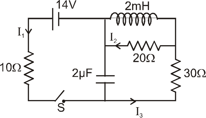 A1.4A,0,0B1.4 A,0.70 A,0.70 AC0,0,0D1.2A,0.6A,0.6A
A circuit contains an ideal cell and an inductor with a switch. Initially, the switch is open. It is closed at t=0. Find the current as a function of time.
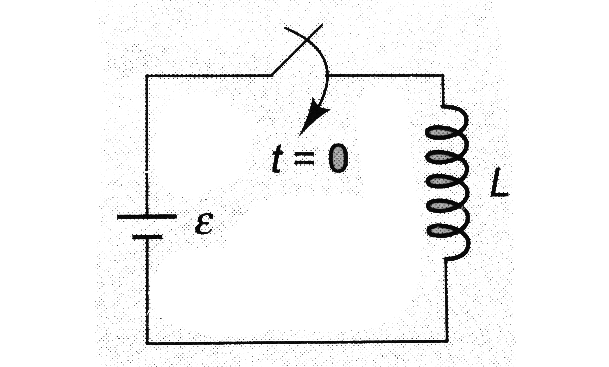
View SolutionTwo parallel plate capacitor of capacitance 2C and C are charged to the potentials 2 V and V respectively and are connected in a circuit along with a resistance R as shown in the diagram. The switch k is closed at t=0. Find the current in the circuit as a function of time and total heat produced in the circuit
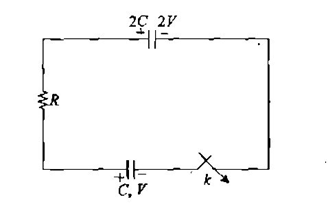
View SolutionIn the circuit shown in figure-5.115, find the current in inductor as a function of time if switch is closed at t=0.
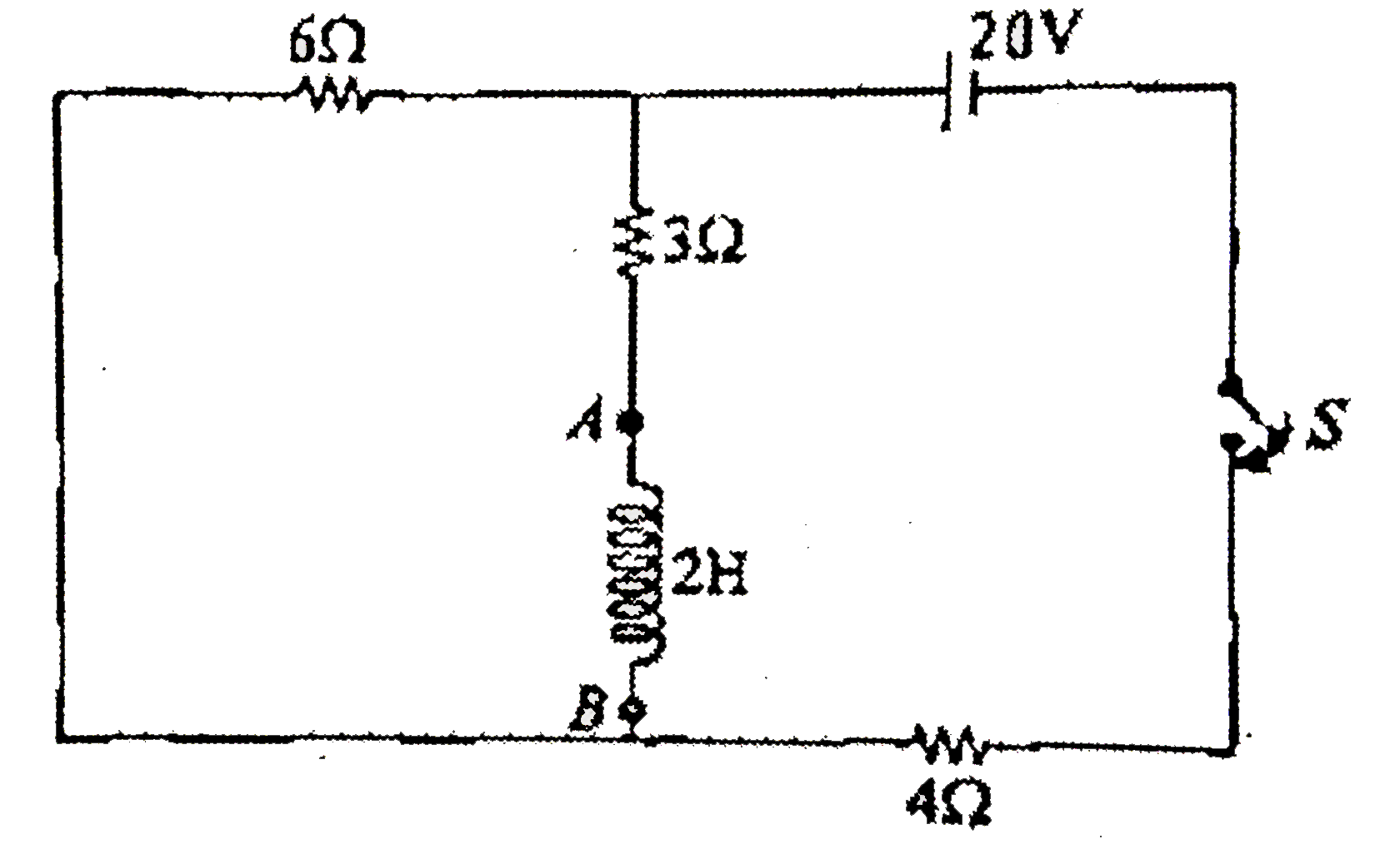
View SolutionFigure-5.102 shows a RL circuit. If at t-0 switch is closed, find the current in inductor as a function of time.
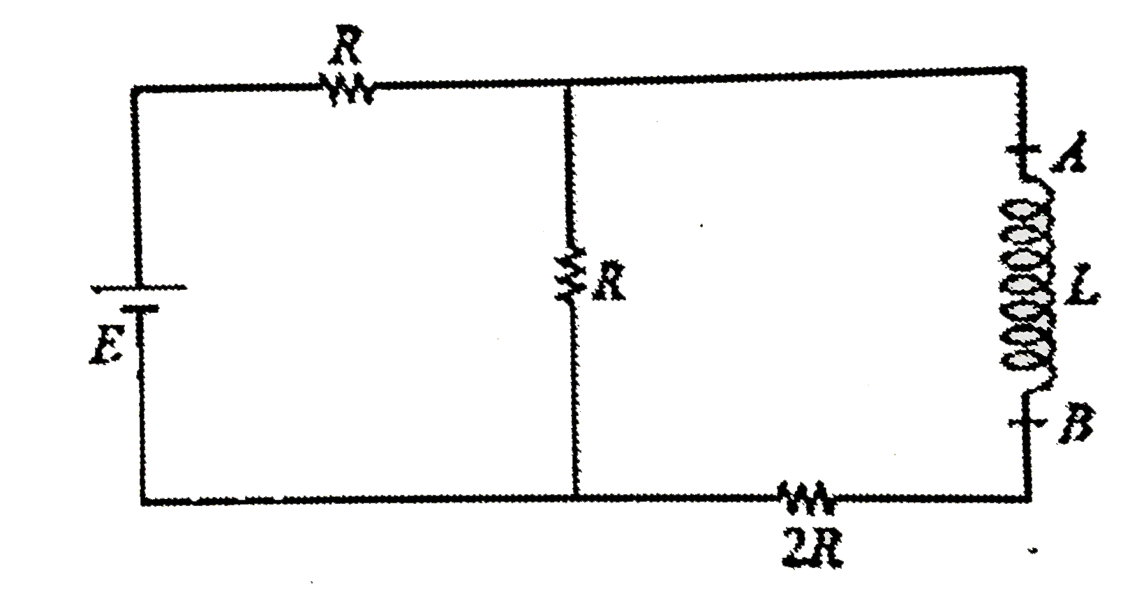
View SolutionIn the LR circuit shown, what is the variation of the current I as a function of time? The switch is closed at time t=0 sec.
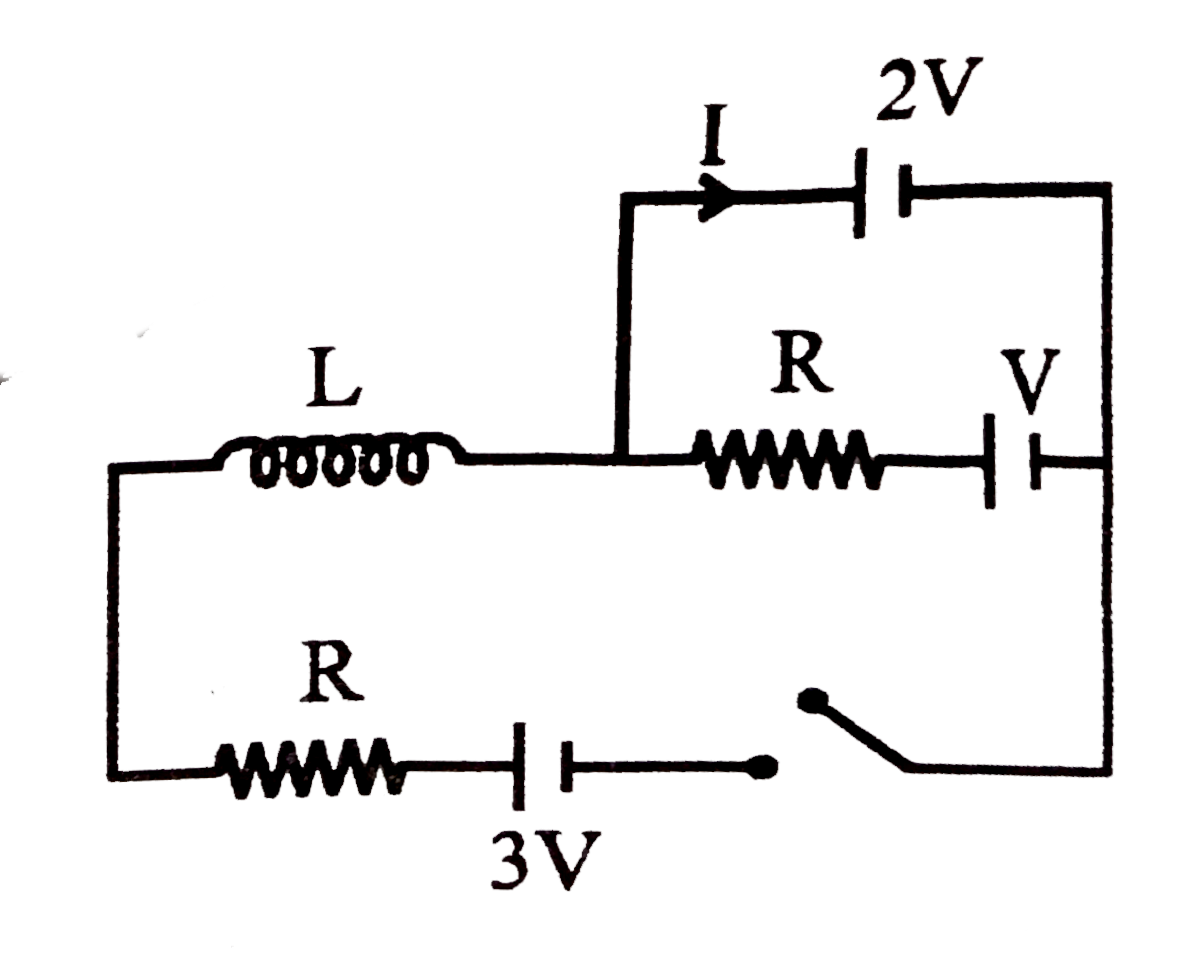
View SolutionSwitch is closed at t=0 then the current in the circuit at t=L2R is
_PHY_E06_157_Q01.png)
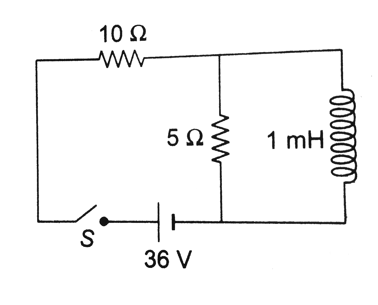
View SolutionIn the circuit arrangement shown in figure, the switch S is closed at t=0. Find the current in the inductance as a function of time? Does the current through 10Ω resistor vary with time or remains constant.
View Solution

