As shown circuit in steady state. If charge on capacitor is 1000μC , find (a) battery current, (b) R1,R2,R3. The current in 50Ω resistor and R2is5A.
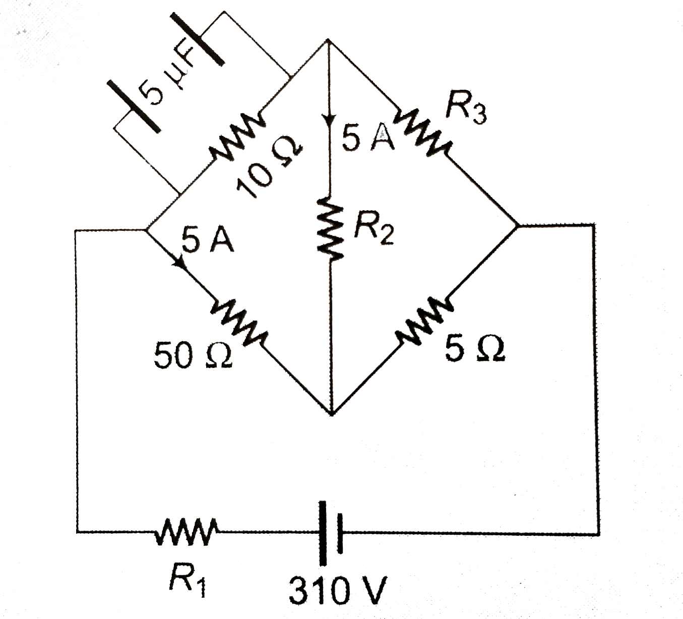

Charging on capacitor = 100μC
p.d. across 5μF = p.d across 10Ω=10005=200V
Current flowing in 10Ω,i0=20010=20A
Battery current i=i0+5=20+5=25A
i0=5+i1⇒20=5+i1⇒i1=15A
Junction D:5+5=i2⇒i2=10A
A to A , path ABDA
VA−i0×10−5R2+5×50=VA
−20×10−5R2+250=0⇒R2=10Ω
B to B path BDCB
VB−5R2−10×5+15×R3=VB
−5×10−50+15R3=0⇒R3=10015=203Ω
A to A path ADCXYA
VA−5×50−10×5+3100⊗xR1=VA
−250−50+310−25R1=0
R1=1025=25=0.4Ω.
Topper's Solved these Questions
- THERMAL AND ELECTRIC EFFECT oF CURRENTBook:CP SINGHChapter:THERMAL AND ELECTRIC EFFECT oF CURRENTExercise:Exercises
Explore 101 Videos
- SEMICONDUCTORSBook:CP SINGHChapter:SEMICONDUCTORSExercise:Exercises
Explore 140 Videos
- WAVE NATURE OF LIGHTBook:CP SINGHChapter:WAVE NATURE OF LIGHTExercise:EXERCISES
Explore 140 Videos
Similar Questions
Knowledge Check
Find the value of R in figure so that there is no current in the 50(Omega) resistor.
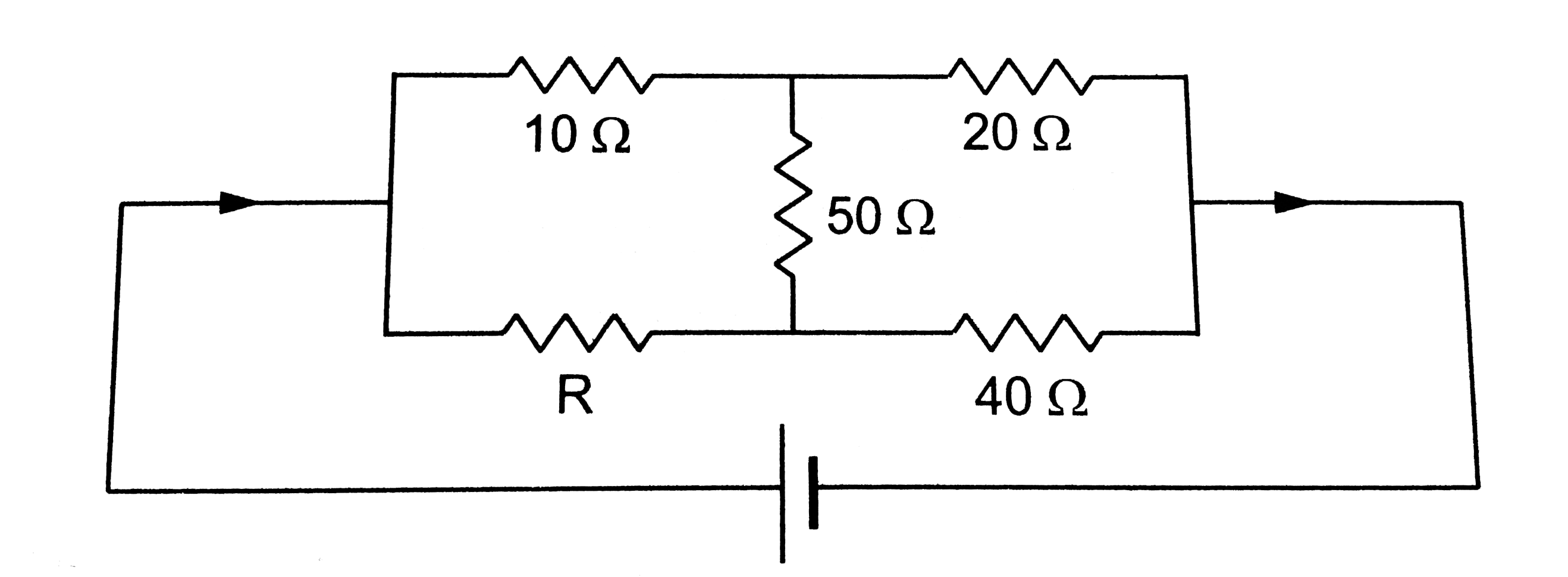 A20B30C40D50
In the shown figures (1) and (2), capacitors are in steady state. Charging batteries are removed a switches S1 and S2 are closed at time t=0. The plot In I (I is the current in the resistor ) against time t the resitors R1 and R2 are shown in the figure. Choose the correct option (s)
(1) AIf ε1=2ε2,R1 must be equal to 2R2BIf R1=R2,C1 must be less than C2CIf C1=C2,R1 must be less than R2DR1C1 is equal to R2C2
In a transistor circuit shown here the base current is 35μA. The value of the resistor Rb is
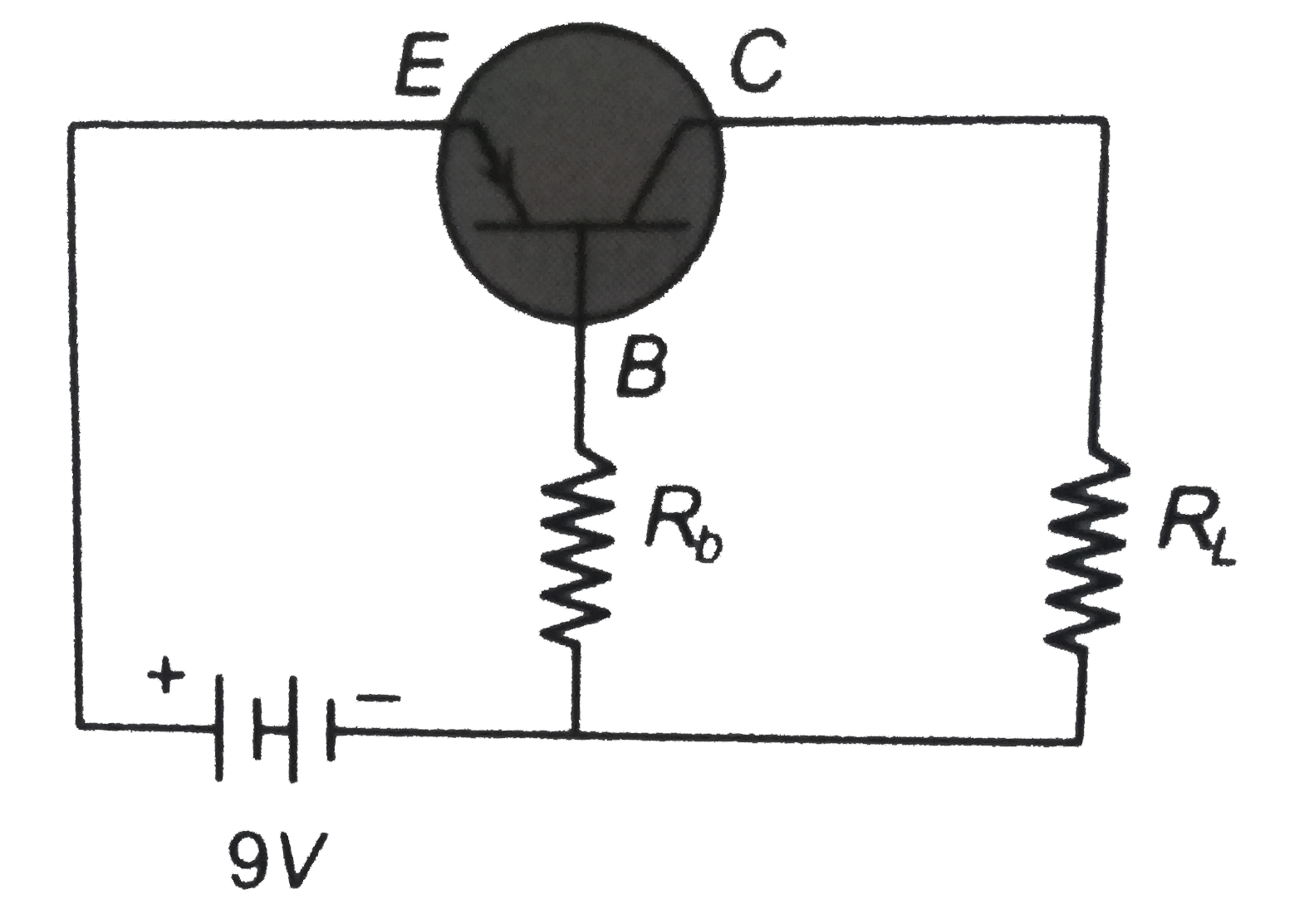 A123.5kΩB257kΩC380.05kΩDNone of these
Steady state current through the circuit shown is R R с Q. 6 R V
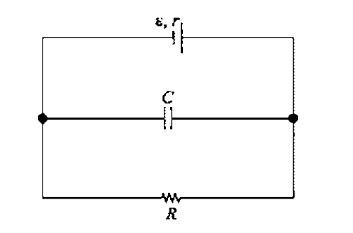
View SolutionThe electric field strength in the capacitor shown in circuit below in steady state is E = 50V/cm. The distance between the· plates of the capacitor C is 0.5 mm, square plates are of area 100cm2, the resistance R=50Ω. and the internal resistance of battery is r=0.1Ω
View SolutionIn the circuit shown in the figure K_(1) is open.The charge on capacitor C in steady state is q_(1) .Now key is closed and at steady state charge on C is q_(2) . The ratio of charges q_(1)/q_(2) is qquad R_(1)=2Omega E
View SolutionThe circuit consists of two resistors (of resistance R1=20Ω and R2=10Ω), a capacitor (of capacitance C=10μF) and two ideal cells. In the circuit shown the capacitor is in steady state and the switch S is open
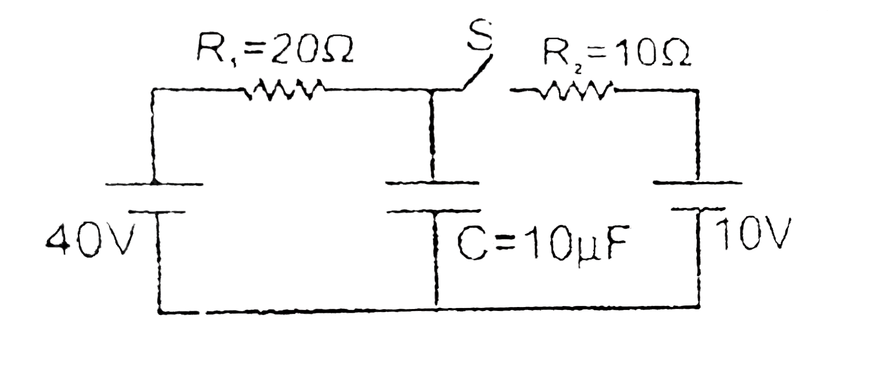
the circuit is in steady state with switch S closed. Now the switch S is opened. Just after the switch S is opened. the current through resistance R1 is
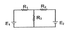
View SolutionIn the circuit shown, E1=7V,E2=7V,R1=R2=1Ω and R3=3Ω respectively. The current through the resistance R3
View Solution


