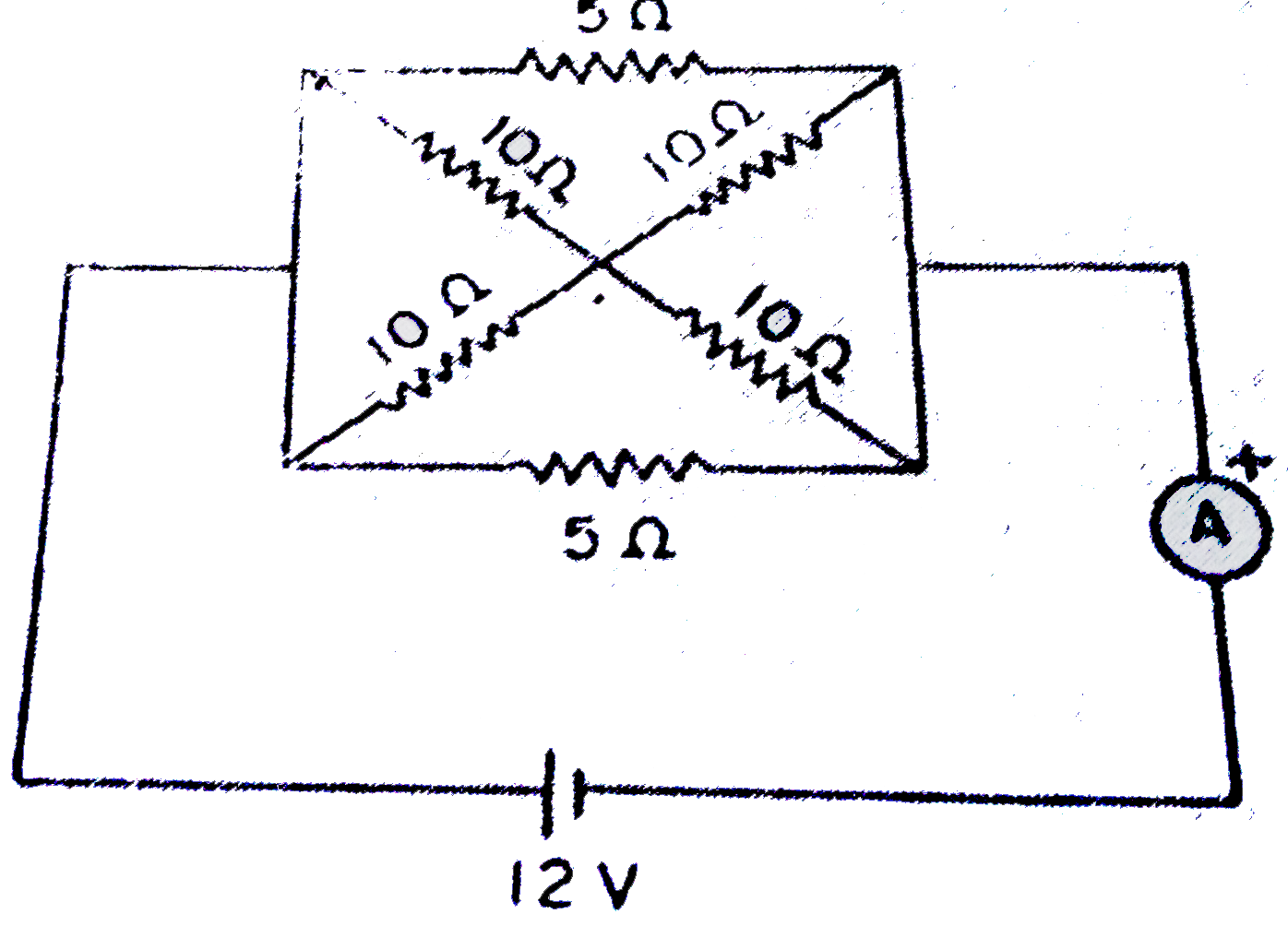
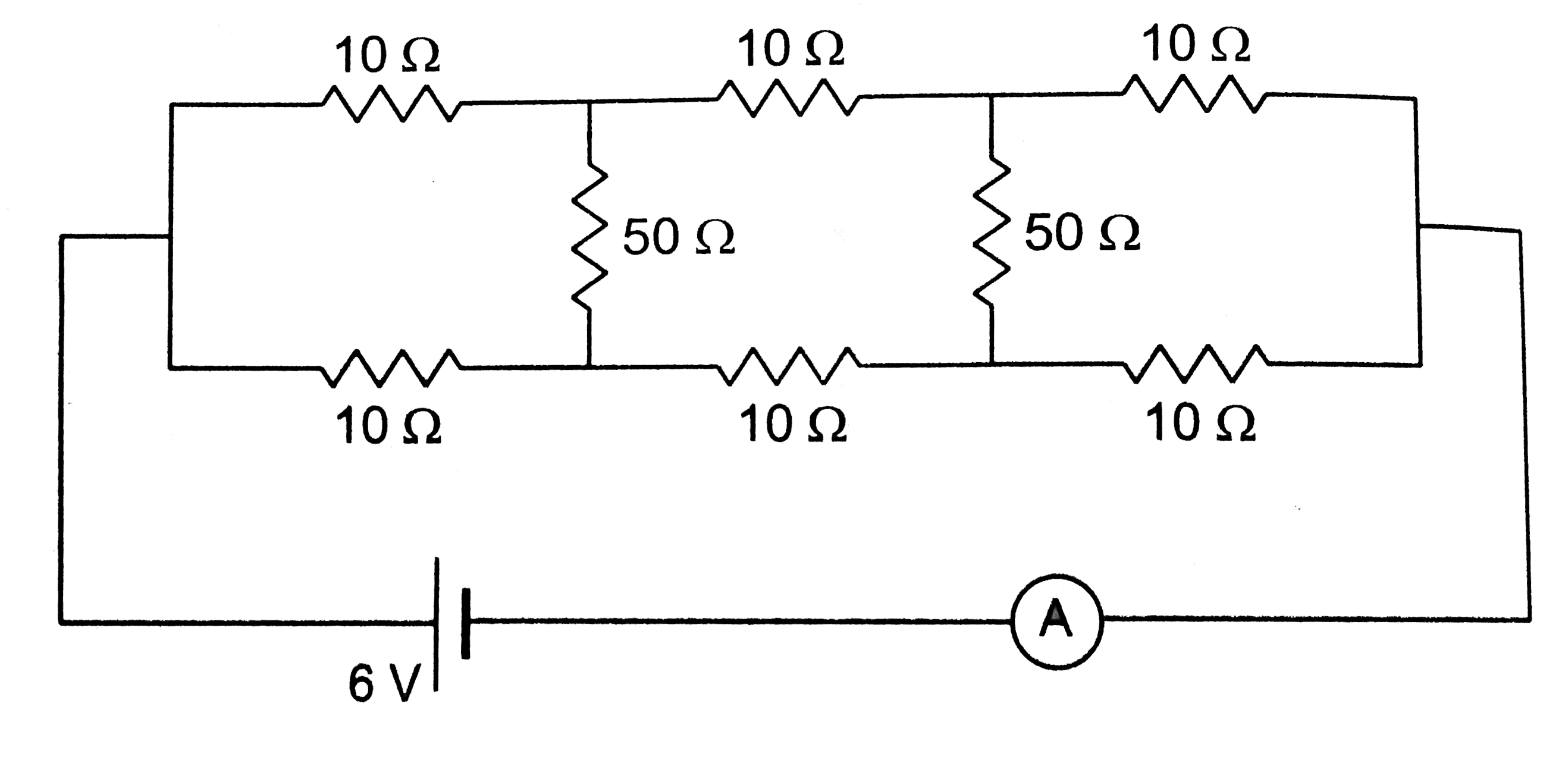
Calculate the current shown by the ammeter A in the circuit diagram
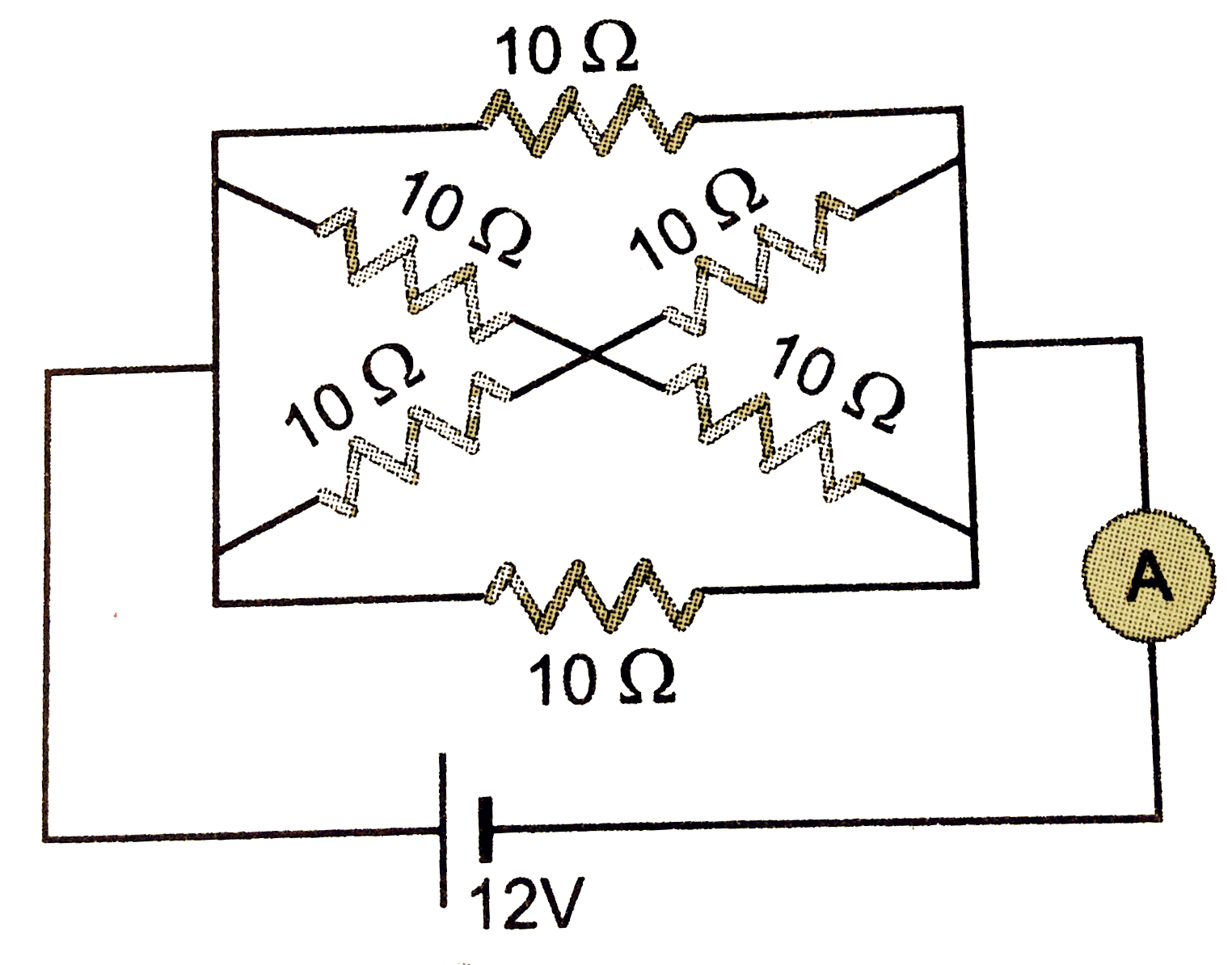
The correct Answer is:3.6A
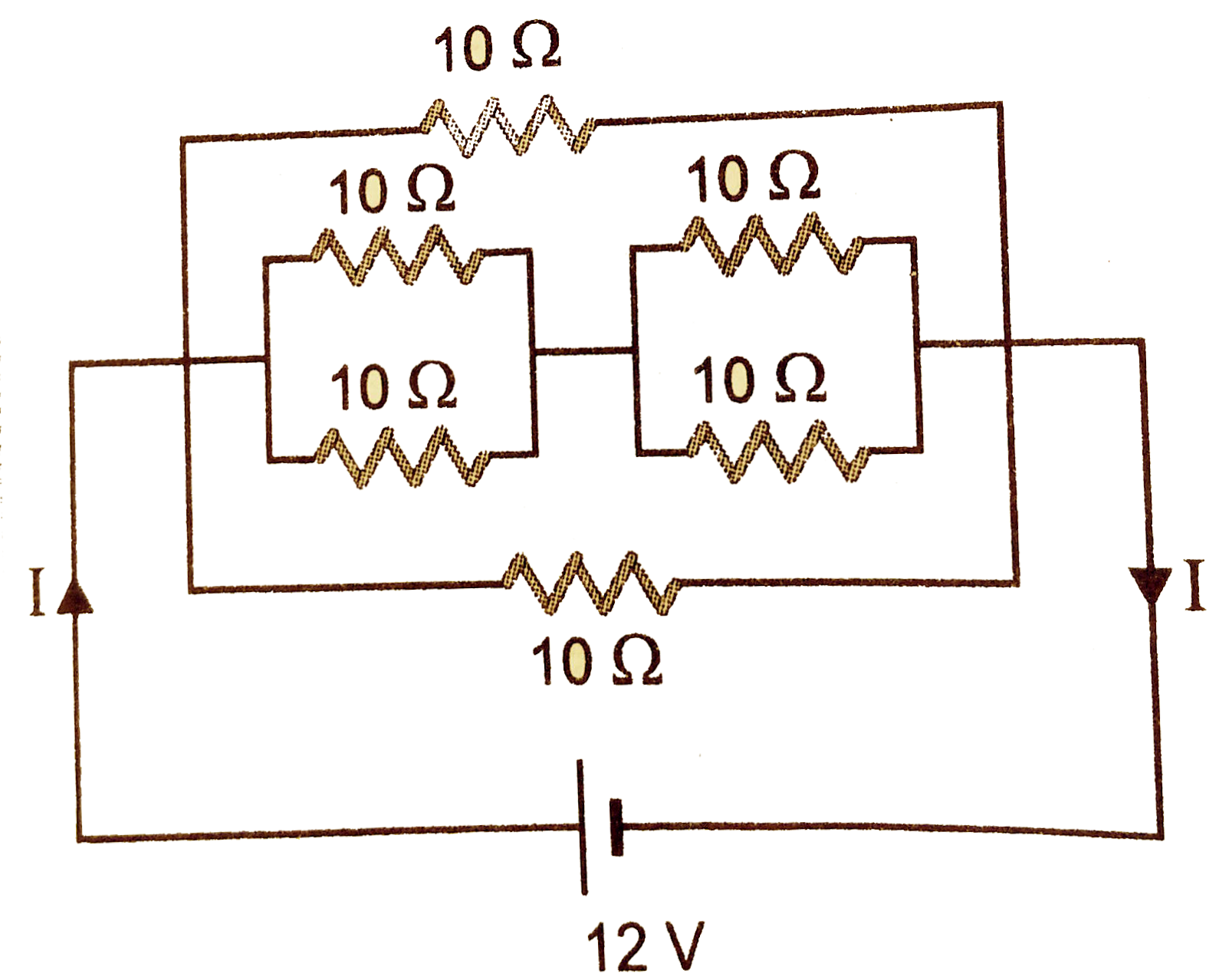
Equivalent circuit is as shown. The resistance of middle arm
=10×1010+10+10×1010+10=5+5=10Ω
Effective resisrtence R of the circuit
1R=110+110+110+310orR=103Ω
Currect I=εR=1210/3=3.6A
Topper's Solved these Questions
- CURRENT ELECTRICITYBOOK - PRADEEPCHAPTER - CURRENT ELECTRICITYEXERCISE - Jee (main and advance)
4 Videos
- CURRENT ELECTRICITYBOOK - PRADEEPCHAPTER - CURRENT ELECTRICITYEXERCISE - Interger Type
2 Videos
- CURRENT ELECTRICITYBOOK - PRADEEPCHAPTER - CURRENT ELECTRICITYEXERCISE - Value based
2 Videos
- COMMUNICATION SYSTEMSBOOK - PRADEEPCHAPTER - COMMUNICATION SYSTEMSEXERCISE - MODEL TEST PAPER-2
9 Videos
- DUAL NATURE OF RADIATION AND MATTERBOOK - PRADEEPCHAPTER - DUAL NATURE OF RADIATION AND MATTEREXERCISE - Exercise
191 Videos
Similar Questions
Calculate the current show by the ammeter A in the circuit diagram
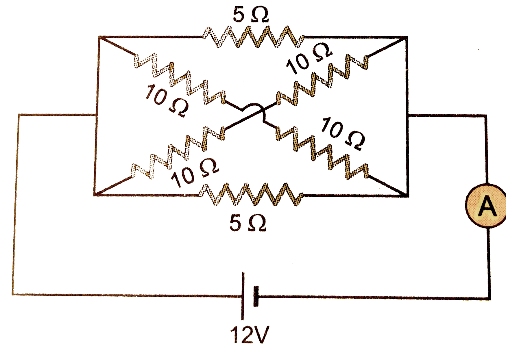
View Solution(a) Two cells of emf ε1 and ε2 having internal resistances r1 andr2 respectively are connected in parallel as shown in Fig. Deduce the expressions for the equivalent emf and equivalent internal resistance of a cell which can replace the combination between the points B1 and B2 . (b) Calculate the current shown by the ammeter in the circuit diagram given below

View Solution
Knowledge Check
In the circuit diagram shown
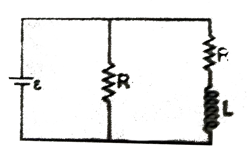 Atime constant is L/RBtime constant is 2L/RCsteady state current in inductor is 2ε/RDsteady state current in inductor is ε/2R
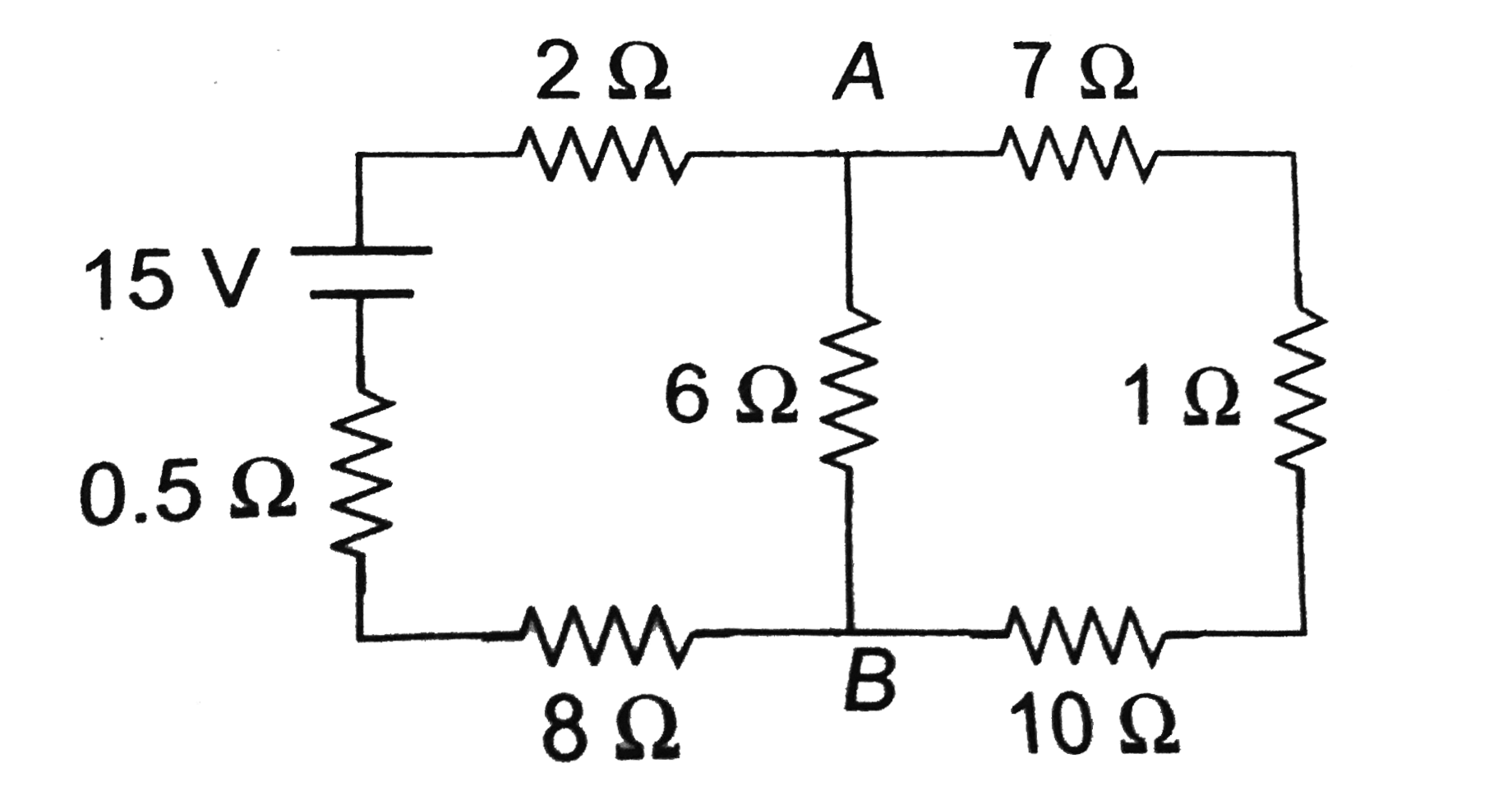
The current from the battery in circuit diagram shown is
 A1AB2AC1.5AD3A
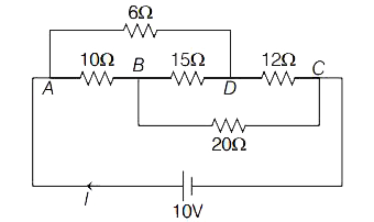
The value of current I as shown in the given circuit diagram is
 A2AB1.5AC0.9AD0.2A
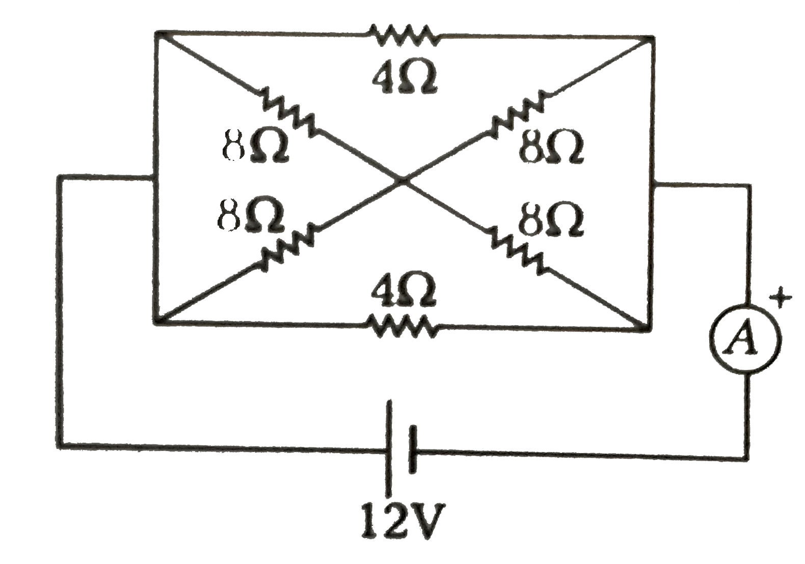
Calculate the current shown by the ammeter A in the circuit shown in figure.
View SolutionCalculate the current shown by the ammeter A in the circuit shown in Fig. 4.47.
View SolutionCalculate the current through the resistace connected across MN and the current supplied by each of the batteries in the circuit diagram shown in
View SolutionFind the current measured by the ammeter in the circuit shown in figure
View SolutionIn the circuit shown in figure current in the circuit is
View Solution
