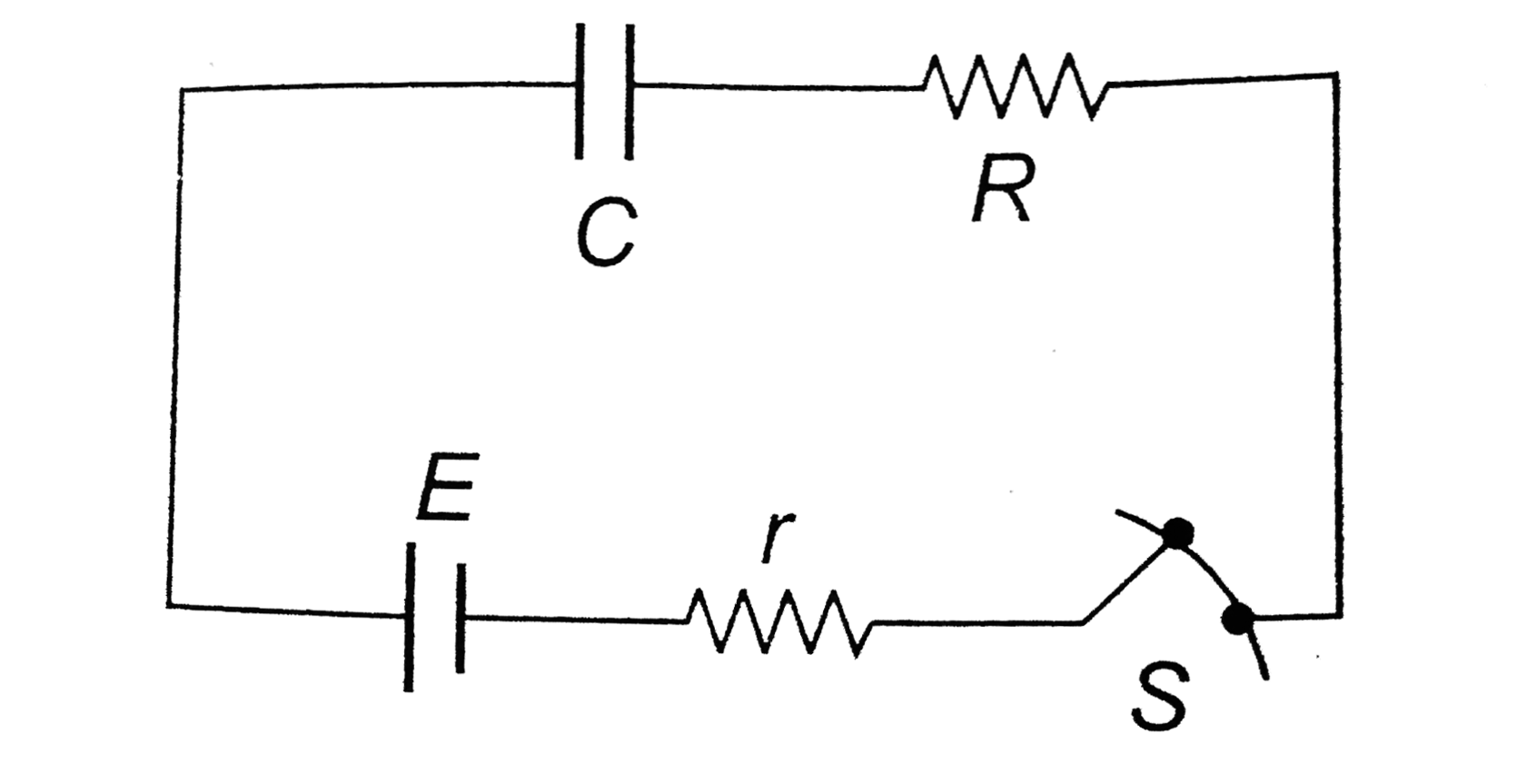
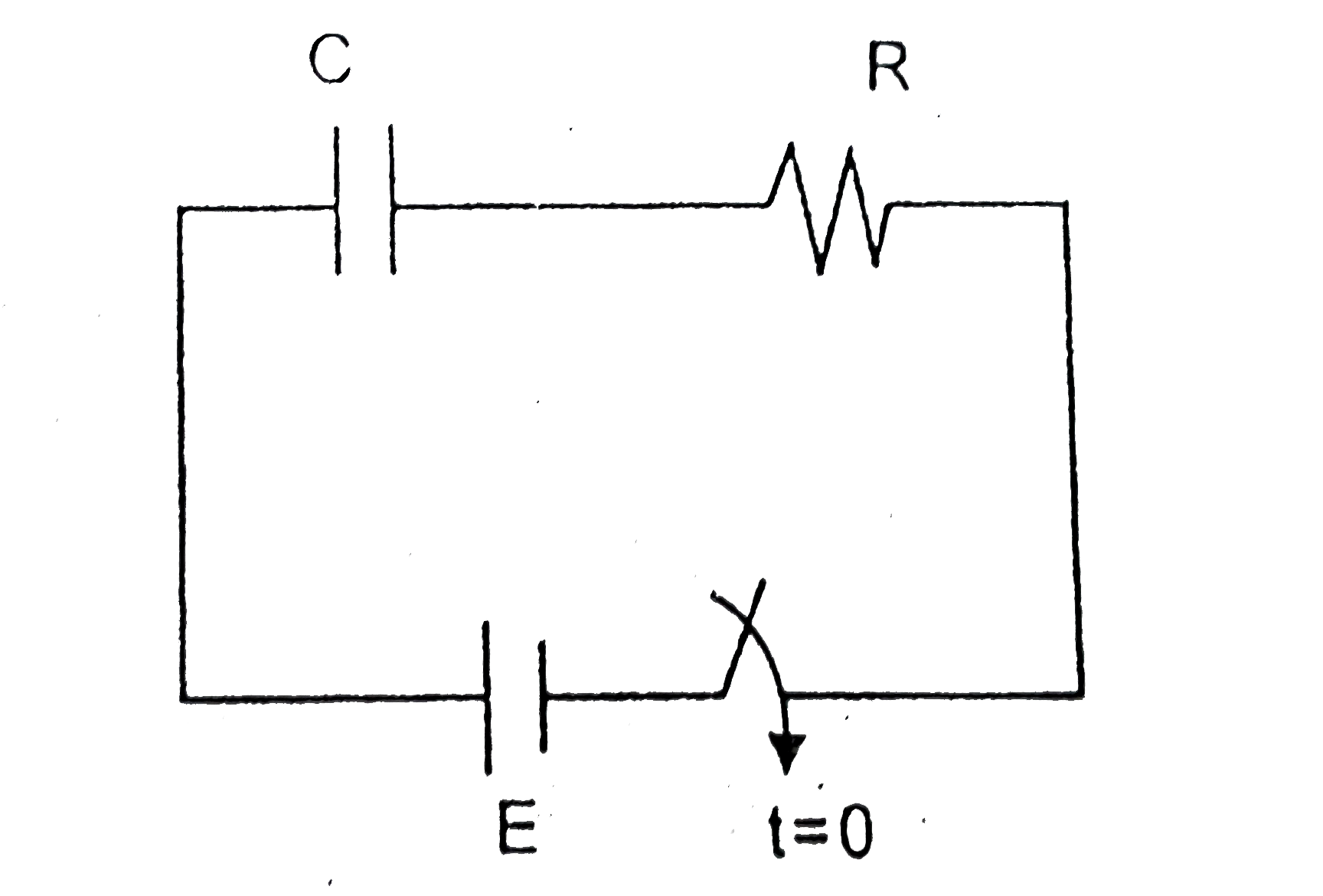
Assertion : The switch S shown in the figure is closed at t=0. Initial current flowing through battery is ER+r
Reason : Initially capacitor was uncharged, so resistance offered by capacitor at t=0 is zero
Statement-1 is True,Statement-2 is True, Statement-2 is a correct explanation for Statement-1
Statement-1 is True,Statement-2 is True, Statement-2 is NOT a correct explanation for Statement-1
Statement -1 is True, Statement-2 is false.
Statement-1 is False, Statement-2 is True.
The correct Answer is:A
Charge on capacitor q=CE(1−e−t/CReq)
∴I=dqdt=EReqe−t/CR
at t=0,I=EReq=ER+r⇒ resistance offered by capacitor is zero,
Similar Questions
Knowledge Check
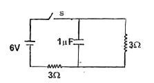
The switch shown in figure is closed at t=0 find the charge throuh battery till time t=LR
_2019_CBT8_E01_016_Q01.png) ALεeR2BLε2eR2C2LεeR2DNone
ALεeR2BLε2eR2C2LεeR2DNoneCharge flow through the battery after closing the switch is (initially all capacitors are unxharged) :
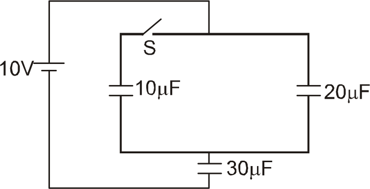 A20mCB30mCC120mCD150mC
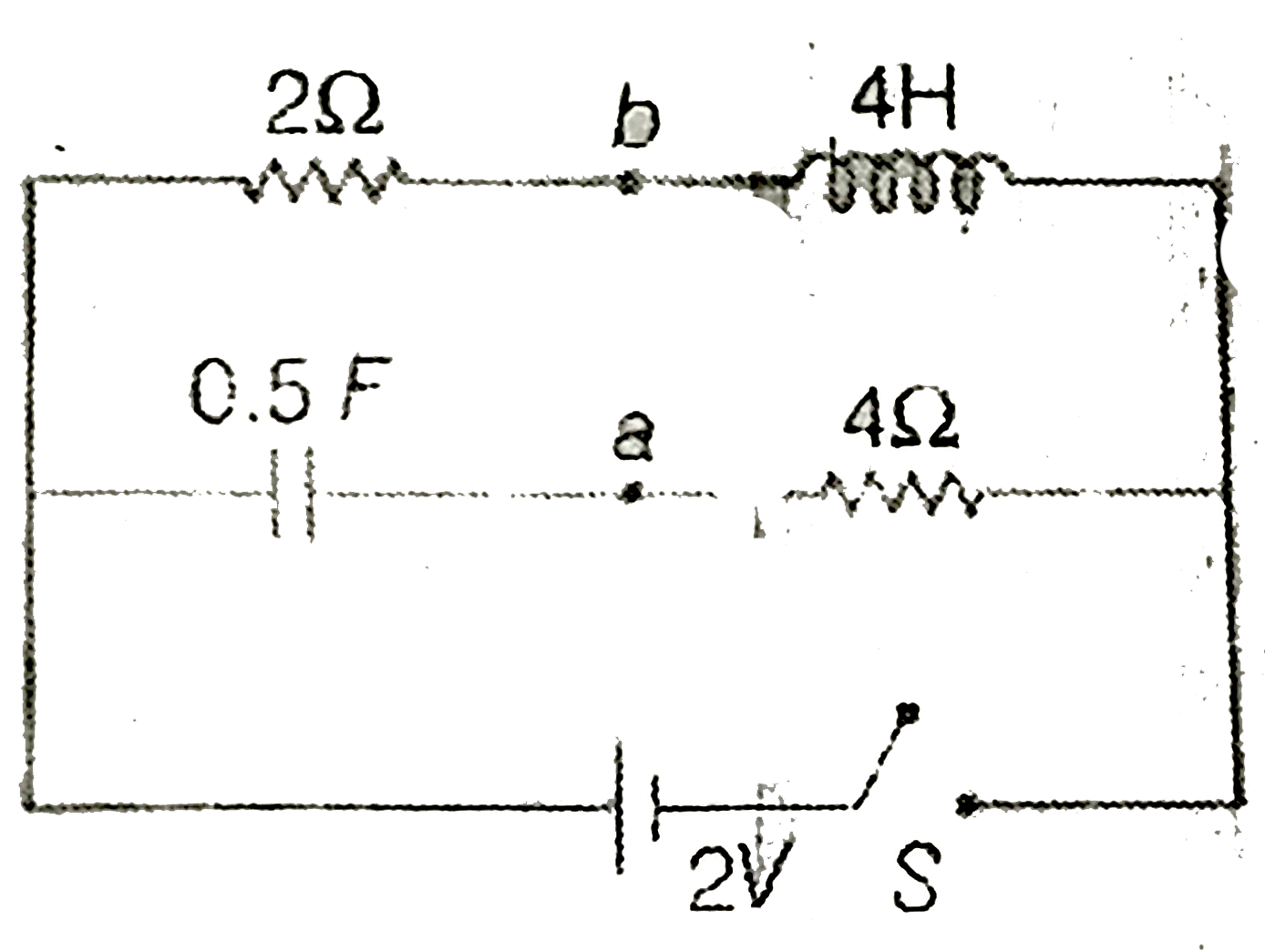
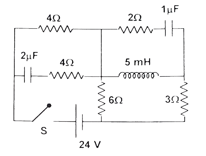
In the circuit shown, the switch 'S' is closed at t=0. Then the current through the battery steady state reached is
 A2AB4AC6AD8A
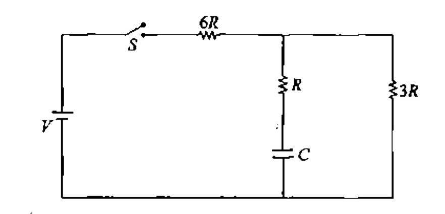
In the circuit shown in figure-3.240 switch S is closed at time t=0. find the current through different wires and charge stored on the capacitor at any time t.
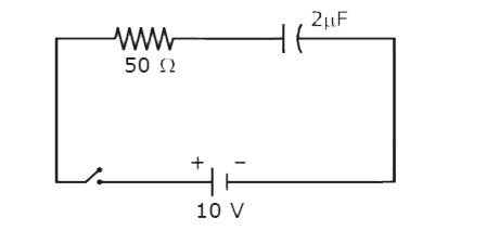
View SolutionFor the circuit shown in figure below, At t = 0, switch is closed, the initial current through resistor and final charge on capacitor are
View SolutionThe current through the battery just after the switch S is Closed is (the capacitors are initially uncharged )
_PHY_E01_002_Q01.png)
View SolutionIn the circuit shown in figure switch S is closed at time t=0
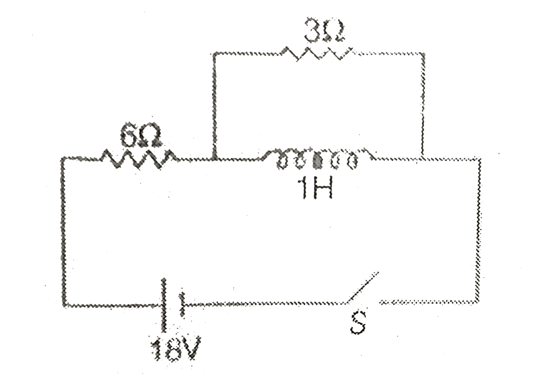
Current I from the battery at time t is given by
View SolutionIn the circuit shown key is closed at t=0 with capacitor initially uncharged.
View Solution

