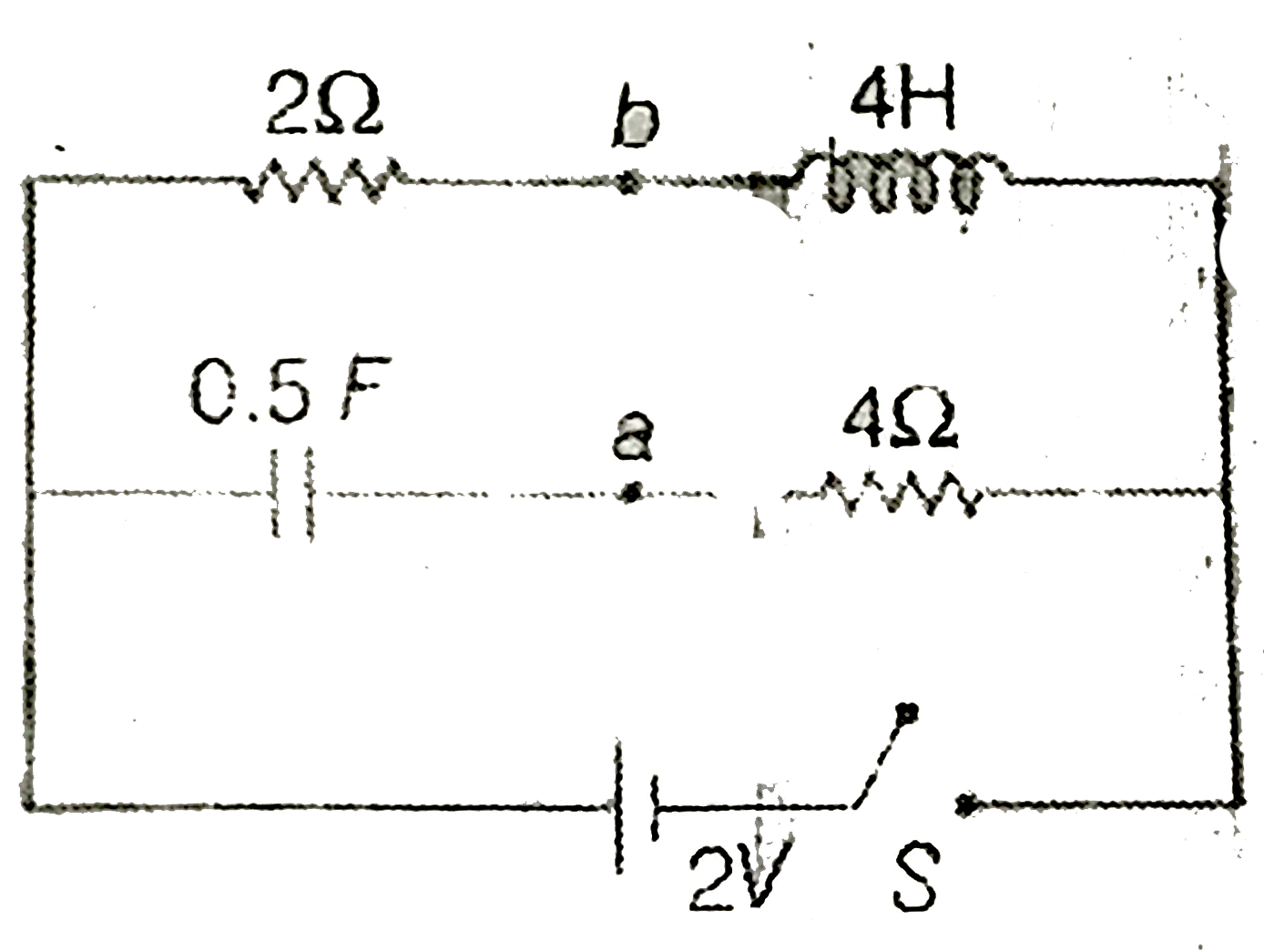
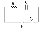
In the circuit shown initially C1,C2 are uncharged. After closing the switch
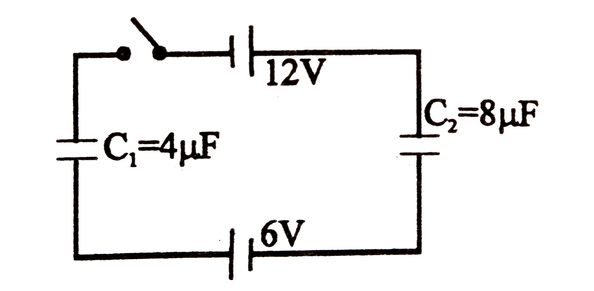
The charge on C2 is greater that on C1
The charge on C1 and C2 are the same
The potential drops across C1 and C2 are the same
The potential drops across C2 is greater than that across C1
The correct Answer is:B
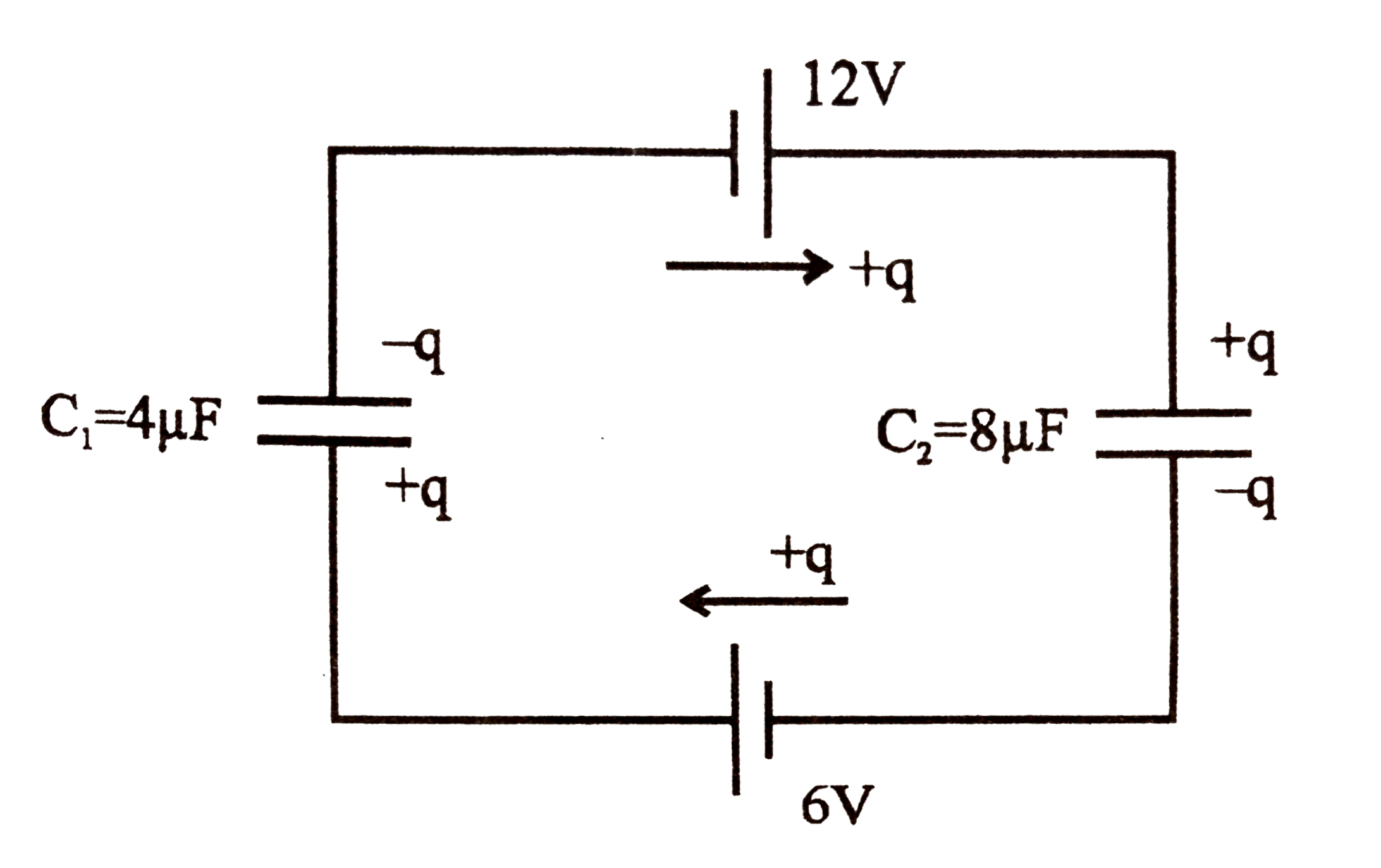
(B) charge on C1 and C2 are same
V2=q8&V1=q4 so V1>V2
Similar Questions
Knowledge Check
In the circuit shown in, C1=6μF,C2=3μF, and battery B=20V. The switch S1 is first closed. It is then opened, and S2 is closed. What is the final charge on C2
 . A120μCB80μCC40μCD20μC
The following two questions refer to the circuit shown. Assume that the capacitors are initially uncharged.
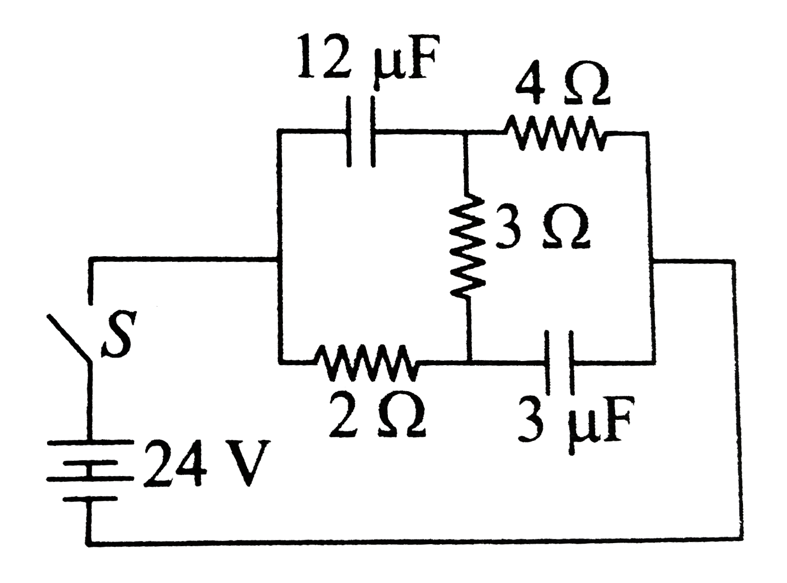
After the switch has been closed for a long time, how much charge is on the positive plate of the 3μF capacitor?A24μCB32μCC56μCD72μCThe capacitor of capacitance C in the circuit shown in fully charged initially. Resistance is R.–
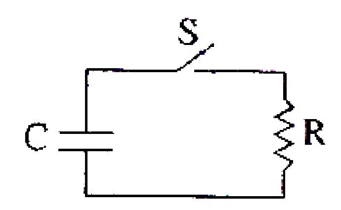
After the switch S is closed, the time taken to reduce the stored energy in the capacitor to half its initial value isARC/2B2RC in 2CRC ln 2DRCln22
In the circuit shown in figure C1=2C2. Capacitance C1 is charged to a potential of V. The current in the circuit just after the switch S is closed is

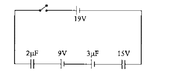
View SolutionThe two capacitors in the circuit shown in figure are initially uncharged and then connected as shown and switch is closed. What is the potential difference across 3μF capacitor?
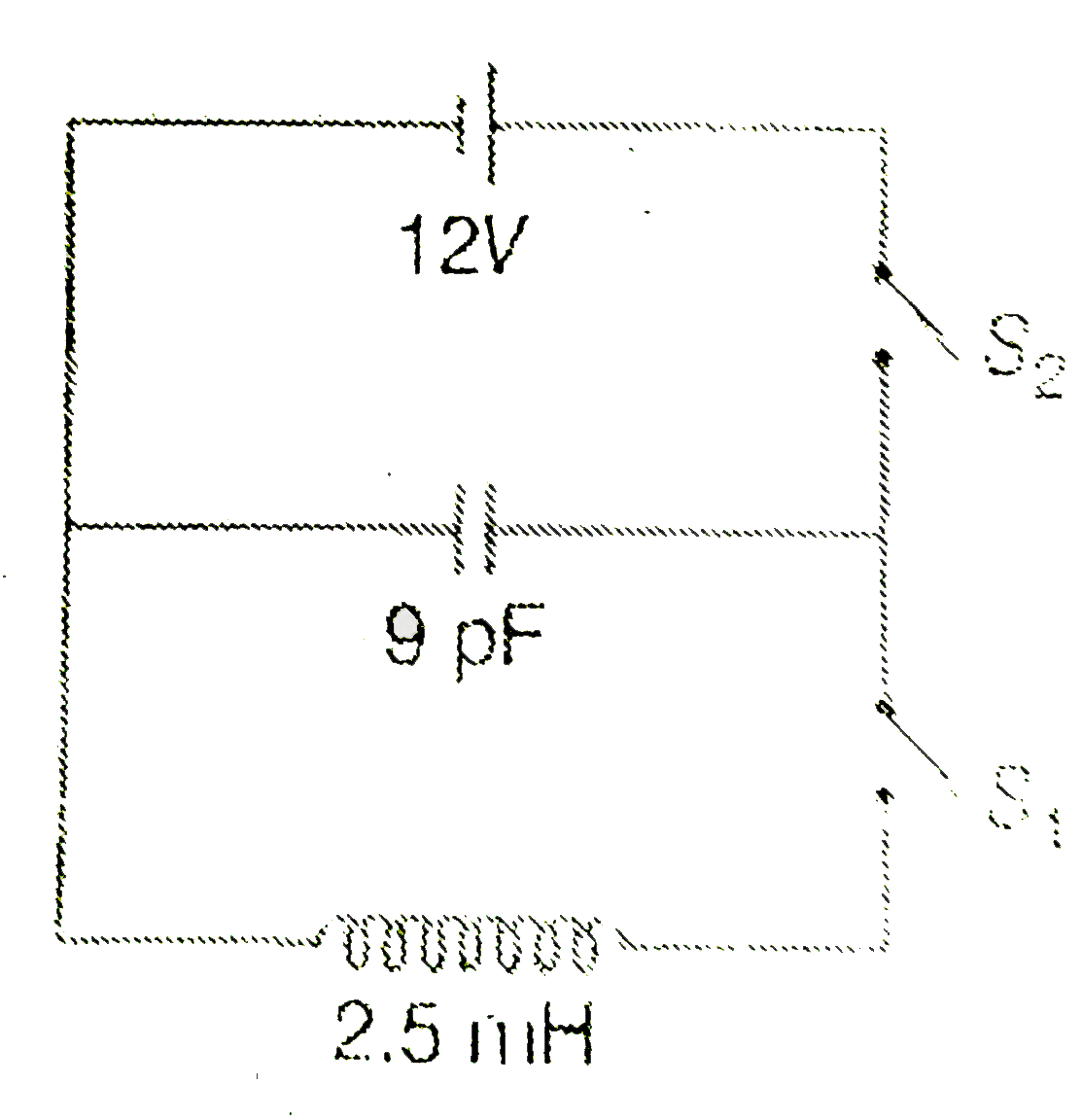
View SolutionIn the circuit shown, the capacitor initially charged with a 12V batteryy, when switch S1 is open and switch S2 is closed. The maximum value of current in the circuit when S2 is opened and S2 is closed is
View SolutionThe capacitor C1 in the figure shown initially carries a charge q0. When the switches S1 and S2 are closed, capacitor C1 is connected in series to a resistor R and a second capacitor C2 which is initially uncharged.
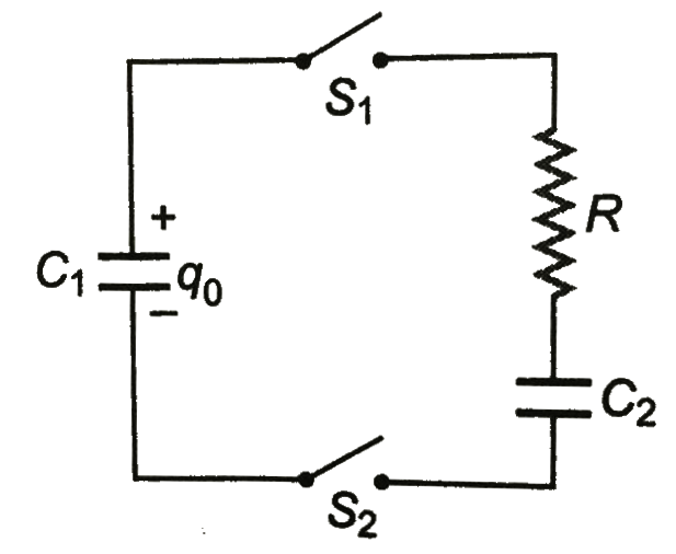
The charge flown through wires as a function of time is
where C=C1C2C1+C2
View Solution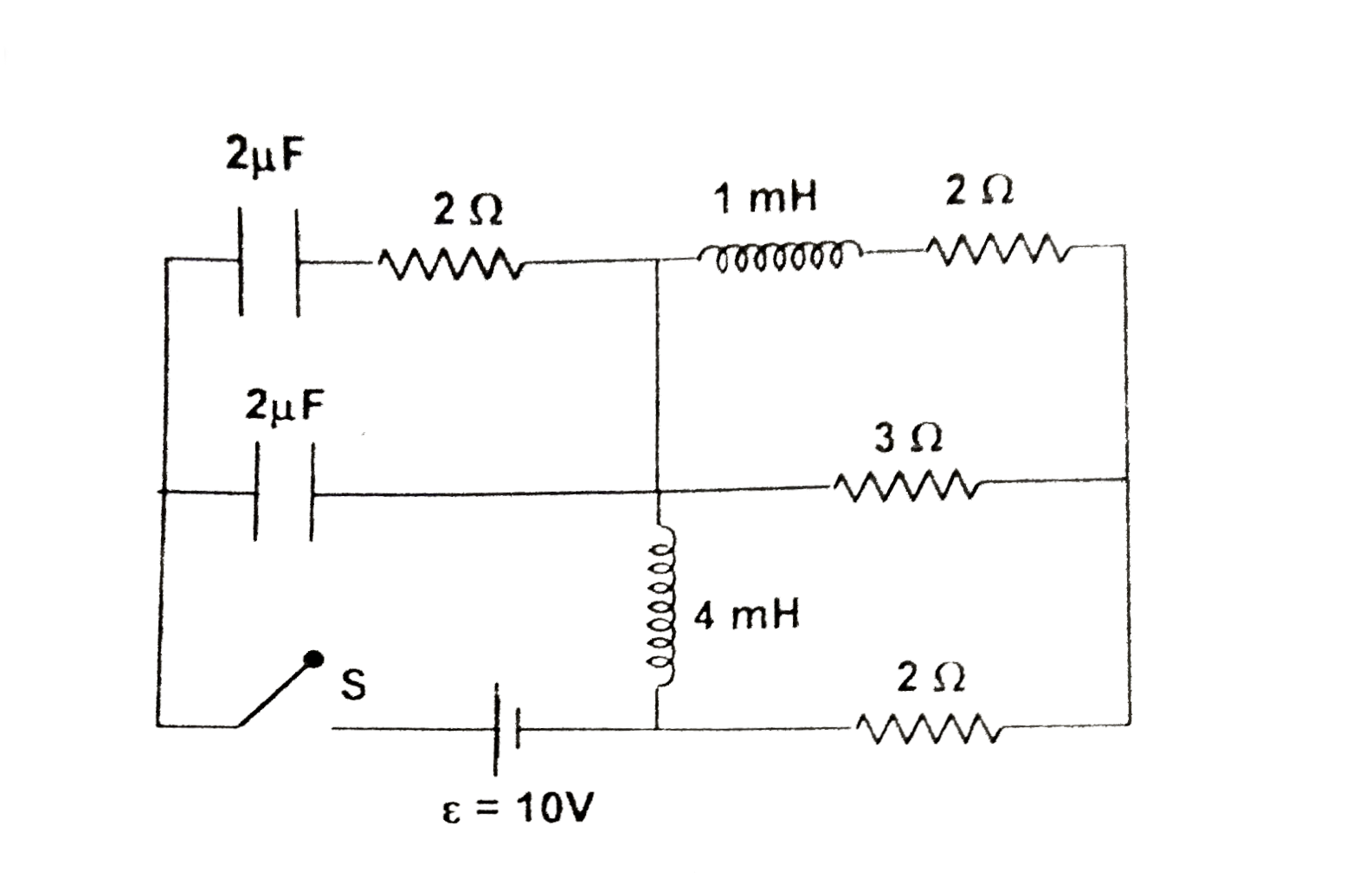
In the circuit shown, all the capacitors are initially uncharged. The current through the battery just after closing the switch 'S' is
View Solution
