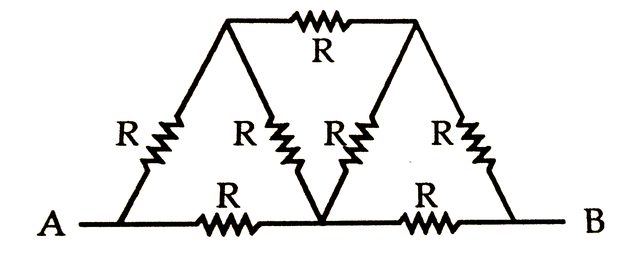
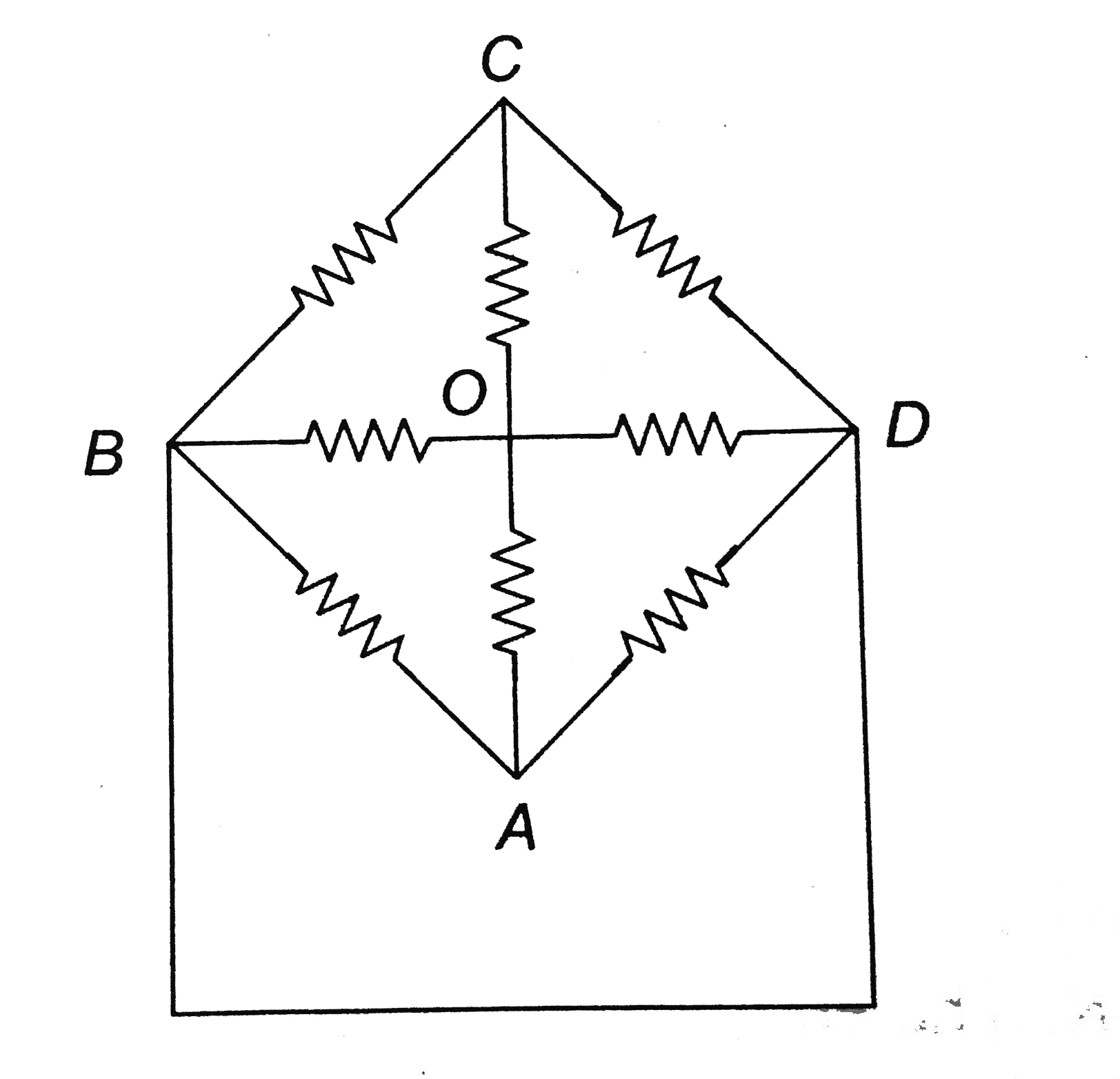
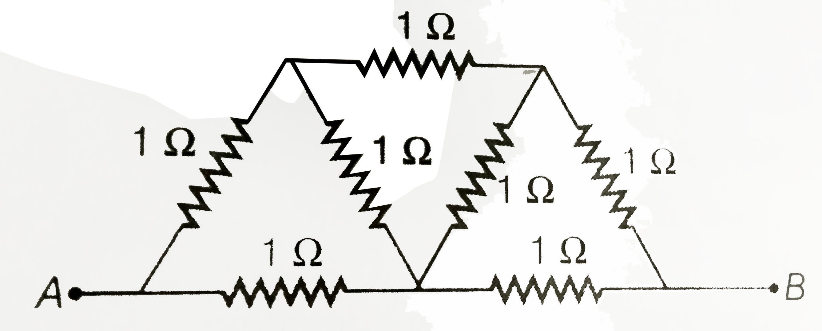
In the diagram below each resistance is of 1Ω. The total resistance between A and B is
A
3/8Ω
B
3/5Ω
C
2/8Ω
D
5/7Ω
Video Solution
Text Solution
The correct Answer is:C
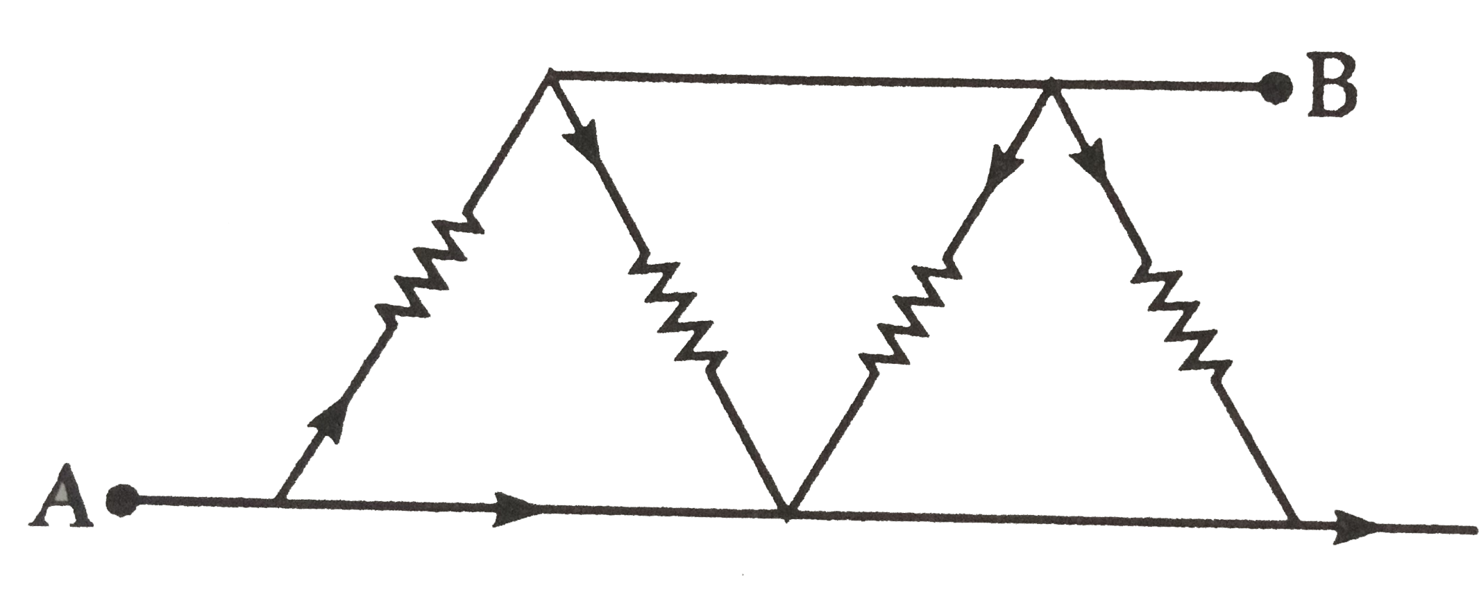
In figure, four resistance are in parallel, Thus, there effective resistance is ,
1Rp=11+11+11+11=41
∴Rp=14=28Ω
|
Topper's Solved these Questions
- CURRENT ELECTRICITYBook:NIKITA PUBLICATIONChapter:CURRENT ELECTRICITYExercise:Multiple Choice Questions
Explore 314 Videos
- COMMUNICATION SYSTEMSBook:NIKITA PUBLICATIONChapter:COMMUNICATION SYSTEMSExercise:Multiple Choice Questions (Examples for Practice)
Explore 8 Videos
- ELASTICITYBook:NIKITA PUBLICATIONChapter:ELASTICITYExercise:MCQ
Explore 314 Videos
Similar Questions
Knowledge Check
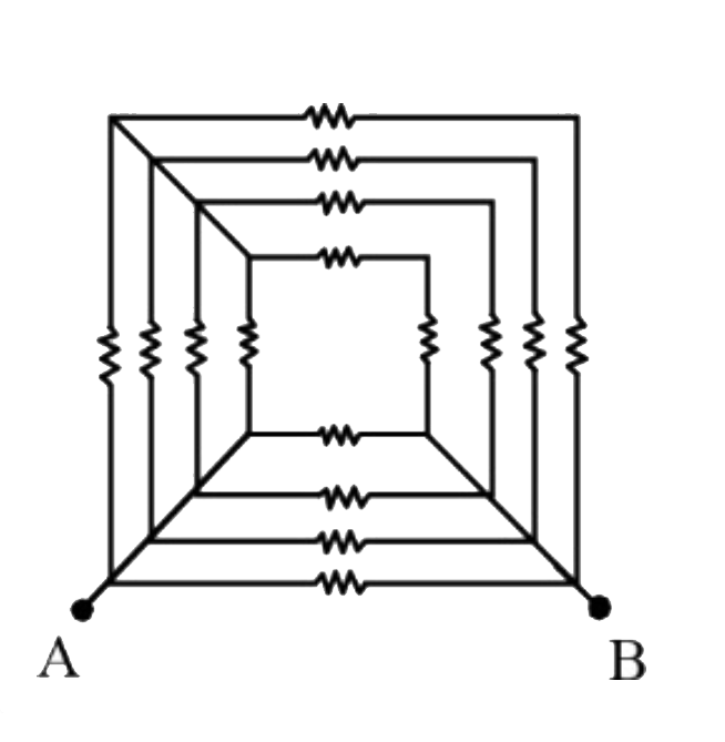
In the adjacent circuit diagram , each resister is of 16Ω . The equivalent resistance between A and B is
 A1ΩB2ΩC3ΩD4Ω
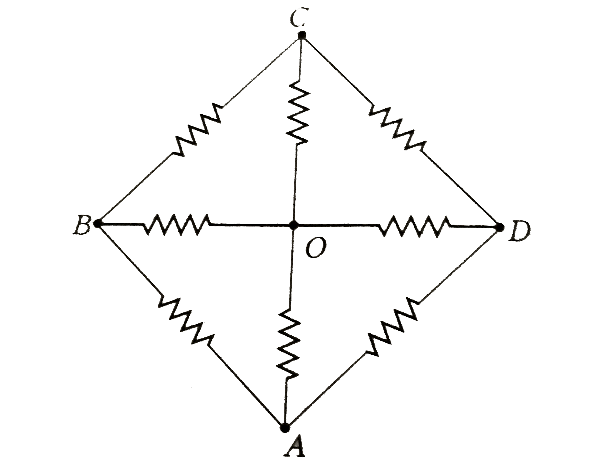
In the arrangement shown, the magnitude of each resistance is 1Ω. The equivalent resistance between O and A is given by
 A1413ΩB34ΩC23ΩD56Ω
In the arrangement shown, the magnitude of each resistance is 2Ω. The equivalent resistance between O and A is given by
 A1415ΩB715ΩC43ΩD56Ω
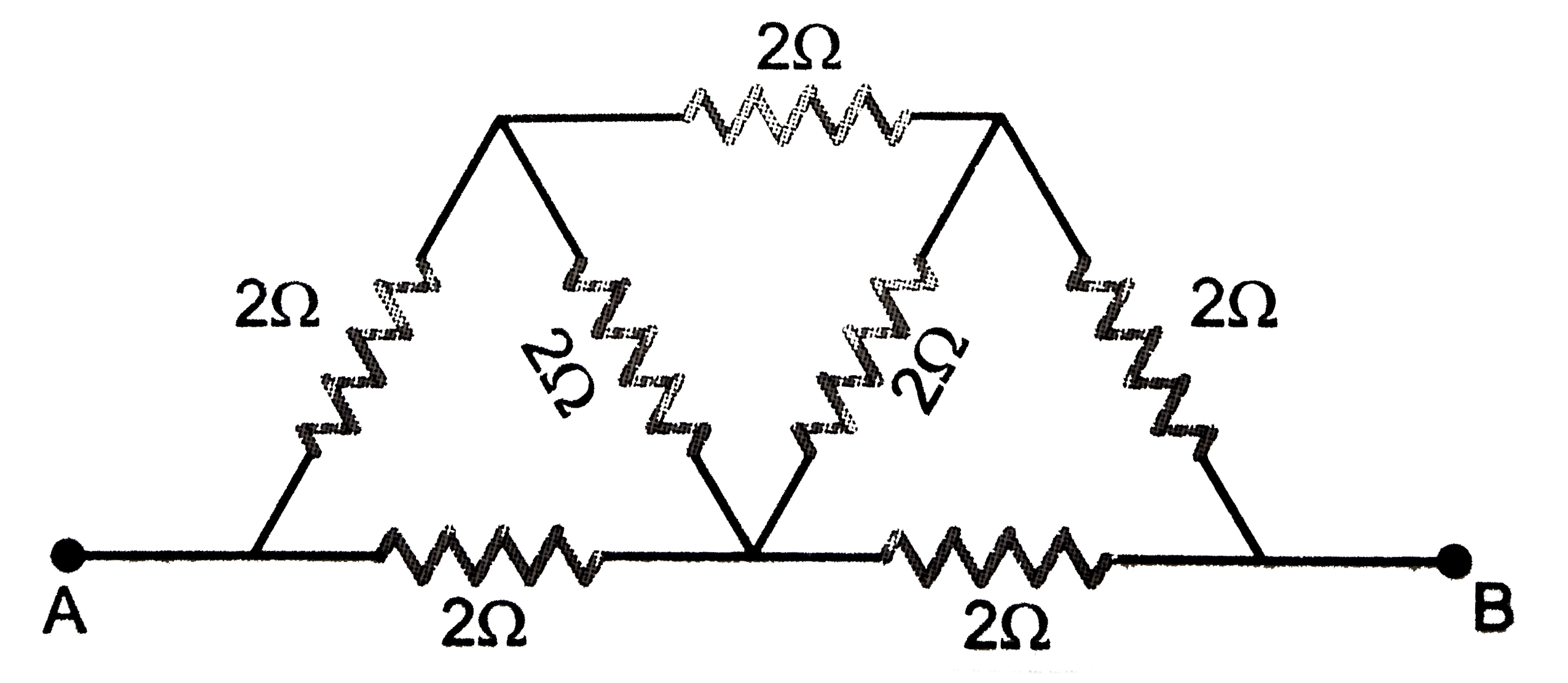
In the net work each resistance is 2Ω. Find th effective resistance between AandB
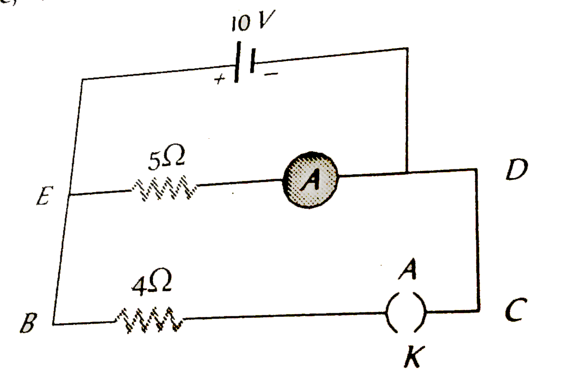
View SolutionIn the figure shown, the total resistance between A and B is
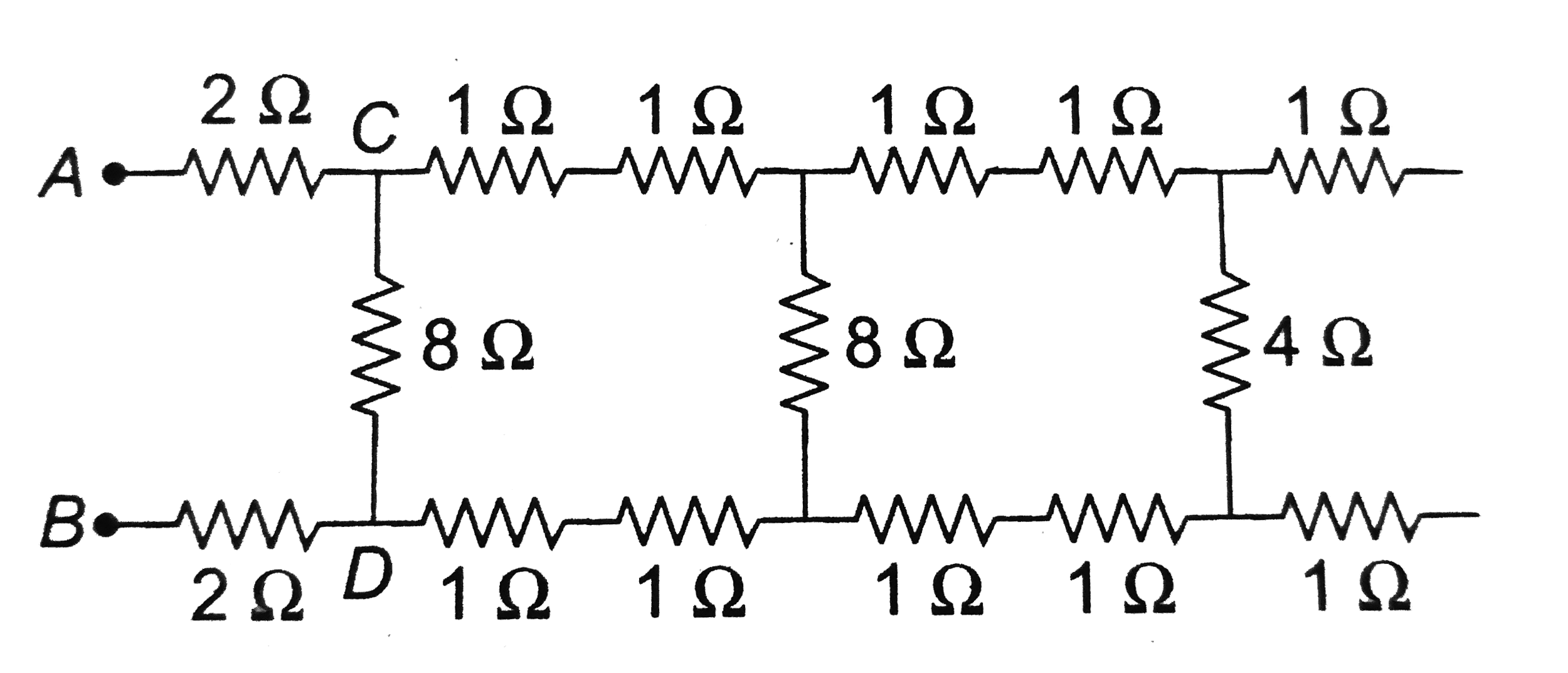
View SolutionIn the figure shown, the total resistance between A and B is
View SolutionIn the network shown in figure each resistance is 1Ω . The effective resistance between A and B is
View SolutionIn the netwrok shown in fig. each resistance is R.
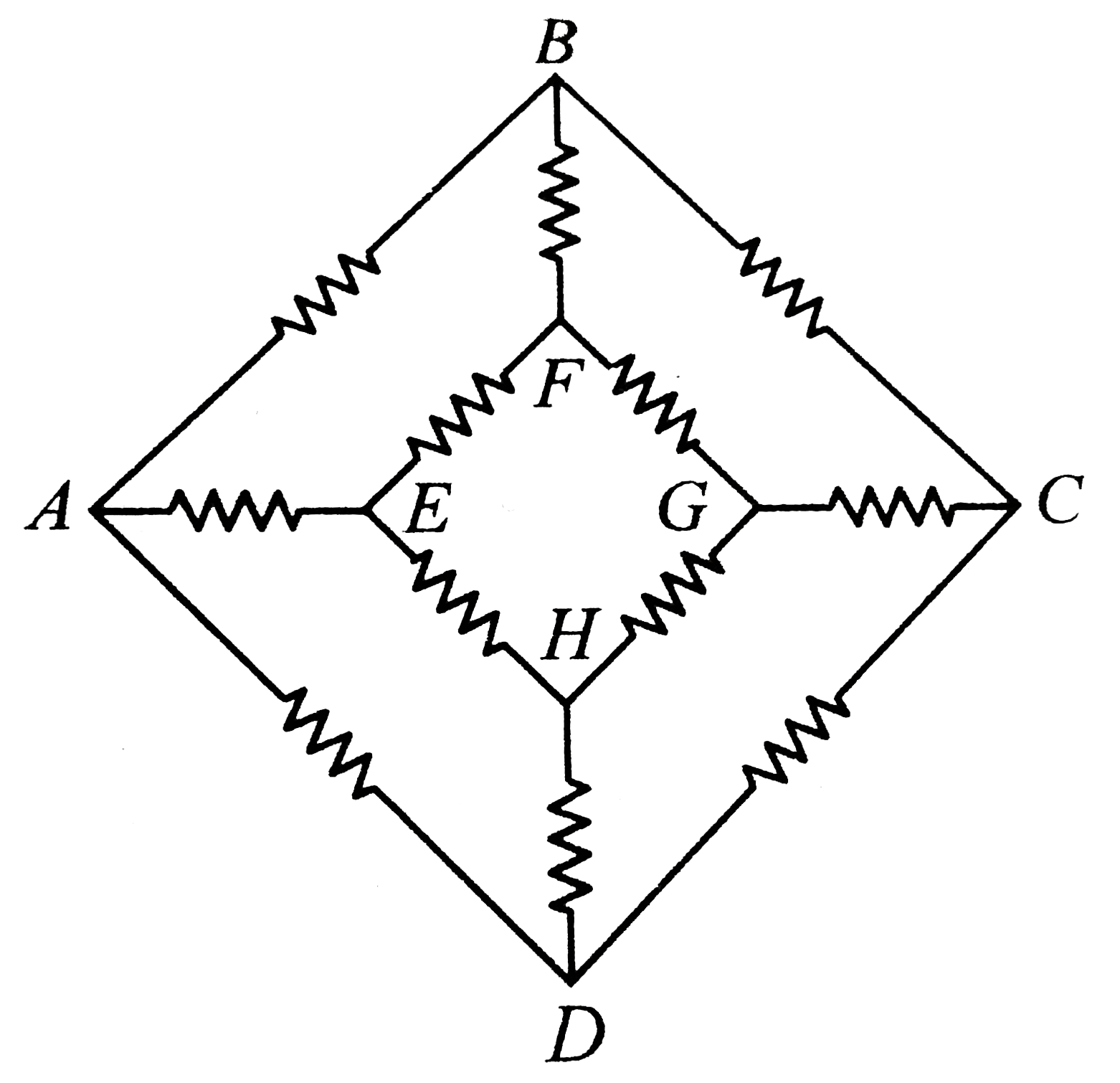
The equivalent resistance between A and B is
View Solution


