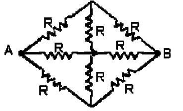
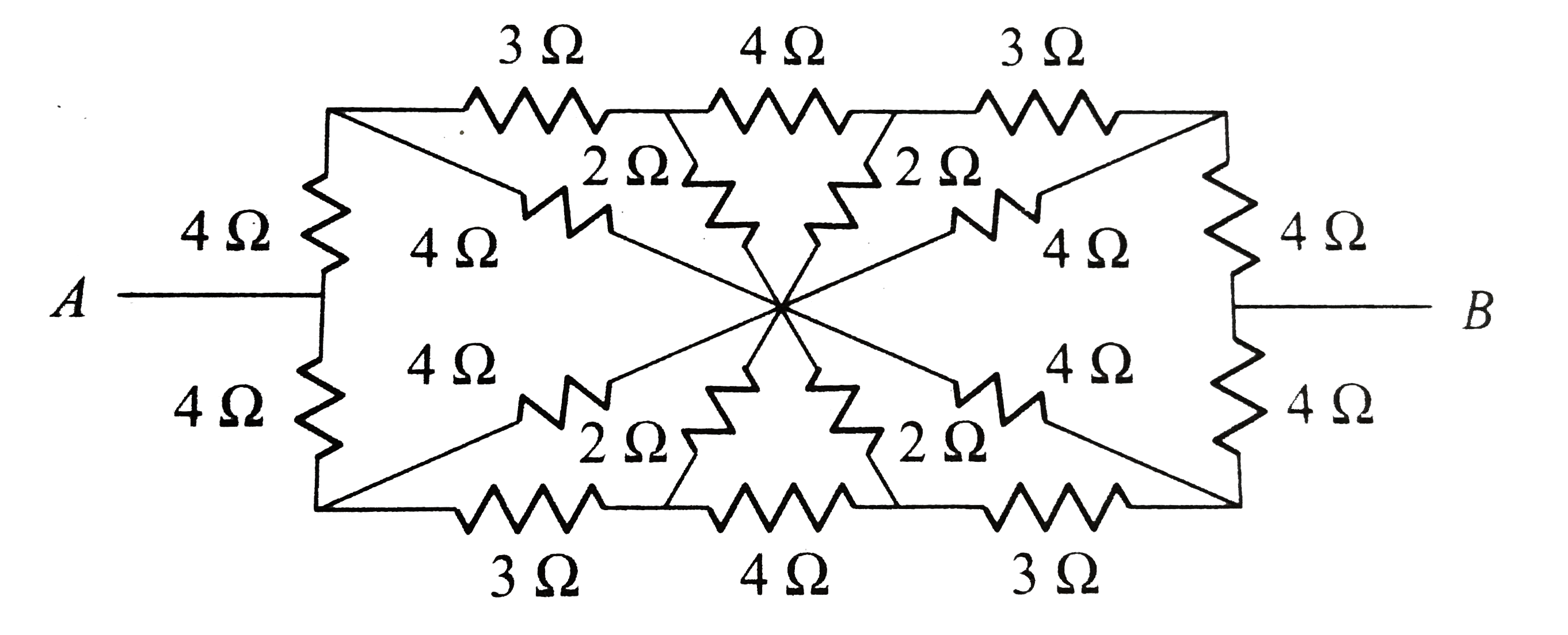
In the figure shown, the total resistance between A and B is
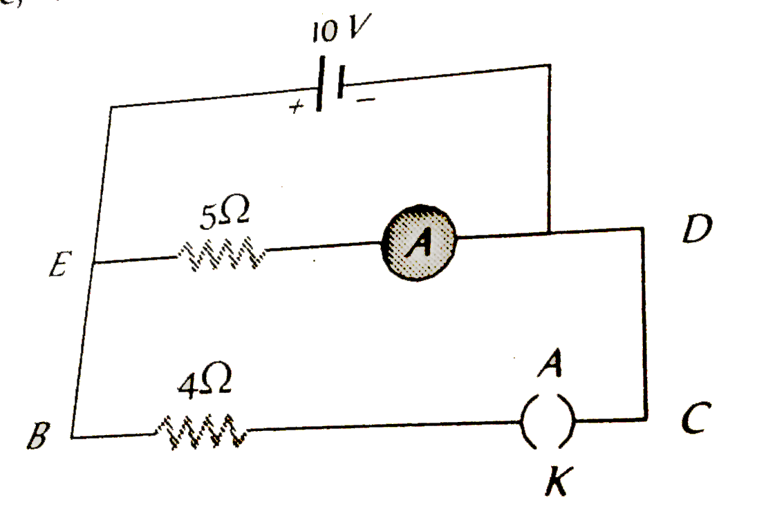
50 A
2A
0.5A
109A
The correct Answer is:B
Step by step video, text & image solution for In the figure shown, the total resistance between A and B is by Physics experts to help you in doubts & scoring excellent marks in Class 12 exams.
Updated on:21/07/2023Topper's Solved these Questions
- CURRENT ELECTRICITYBOOK - ERRORLESS CHAPTER - CURRENT ELECTRICITYEXERCISE - Kirchhoff s Law, cells
8 Videos
- CURRENT ELECTRICITYBOOK - ERRORLESS CHAPTER - CURRENT ELECTRICITYEXERCISE - Different Measuring Instruments
1 Videos
- COMMUNICATION SYSTEMBOOK - ERRORLESS CHAPTER - COMMUNICATION SYSTEMEXERCISE - S E T
14 Videos
- ELECTRO MAGNETIC INDUCTIONBOOK - ERRORLESS CHAPTER - ELECTRO MAGNETIC INDUCTIONEXERCISE - SET
20 Videos
Similar Questions
Knowledge Check
In the circuit shown in figure the total resistance between points A and B is R0. The value of resistance R is
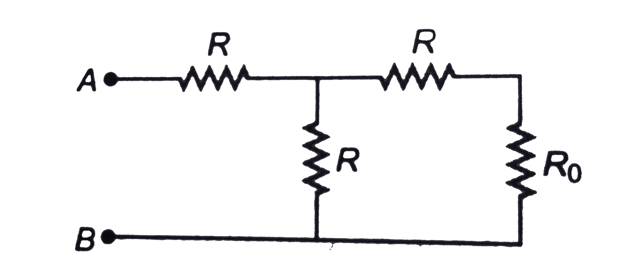 AR0B√3R0CR02DR0√3
In the network shown in the figure, the equivalent resistance between A and C is
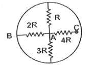 A10 RB(6/11)RC(12/15)RD(50/11)R
Thirteen resistances each of resistance R ohm are connected in the circuit as shown in the figure below. The effecitve resistance between A and B is
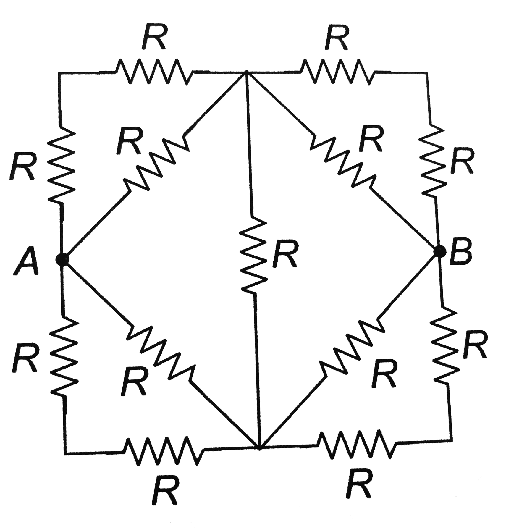 A2RΩB4R3ΩC2R3DRΩ
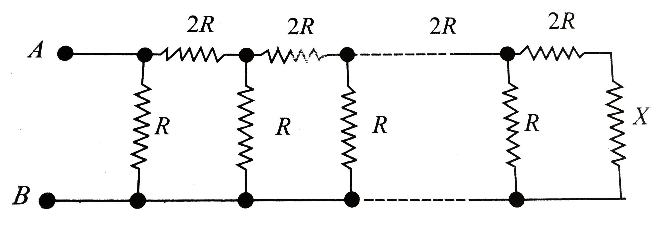
At what value of the resistance in the circuit shown in the figure will the total resistance between points A and B be independent of the number of cells? If R=(√3+1)Ω, then the value of x will be ……..Q.
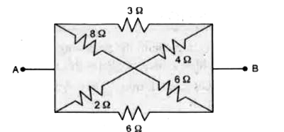
View SolutionIn the circuit arragement shown in the figure , the equivalent resistance between points A and B :
View SolutionCalculate the current in the various branches of 10Ω resistance of the network of resistance as shown in figure
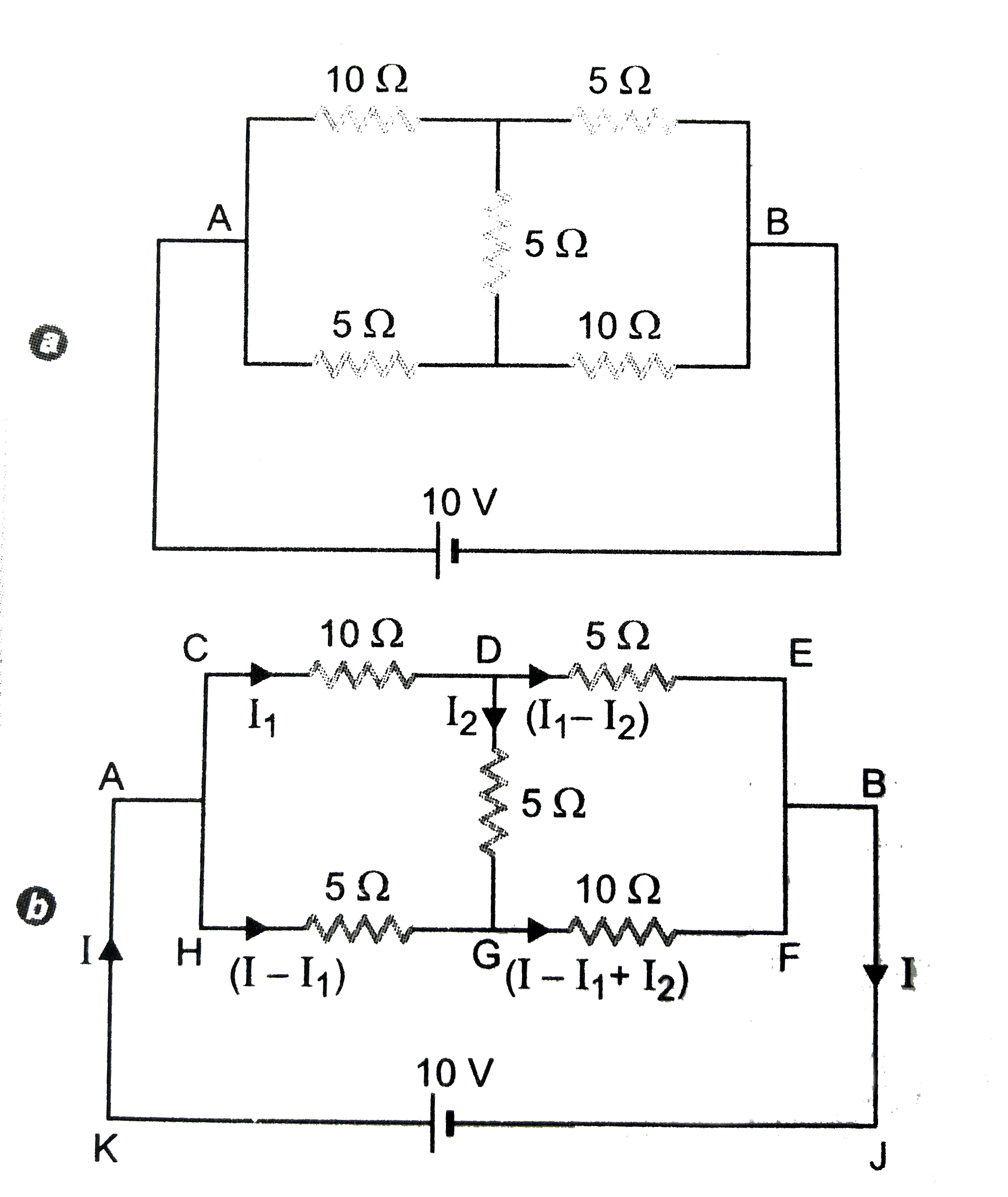 .
.
Also calculate the total resistance between A and B.
View SolutionA number of resistors are connected as shown in the figure. The equivalent resistance between A and B is
View SolutionA frame is formed by nine identical wires of resistances R each as shown in the figure.
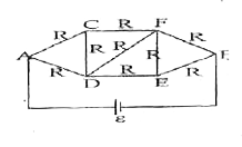
The equivalent resistance between A and B is
View Solution

