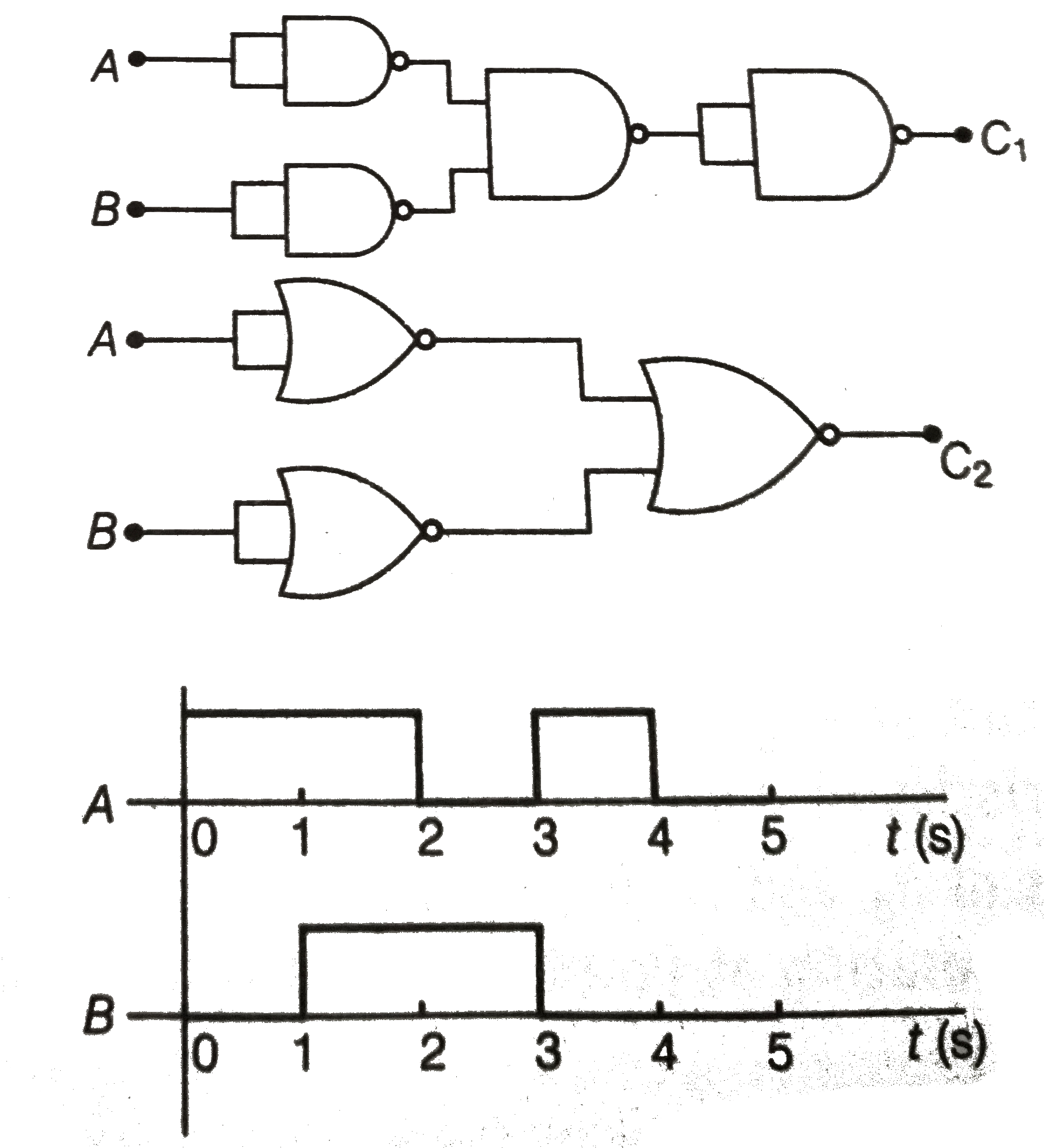
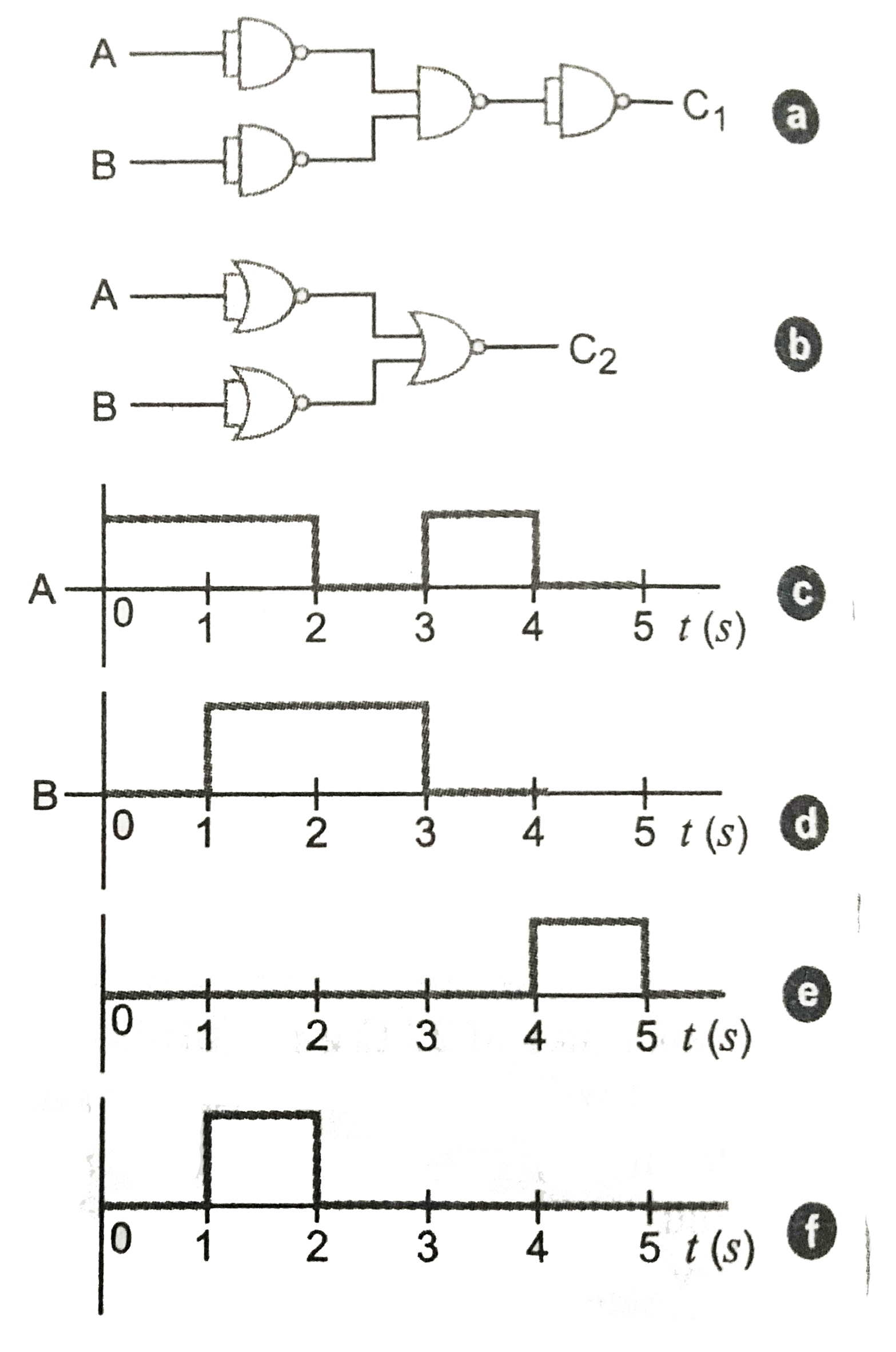
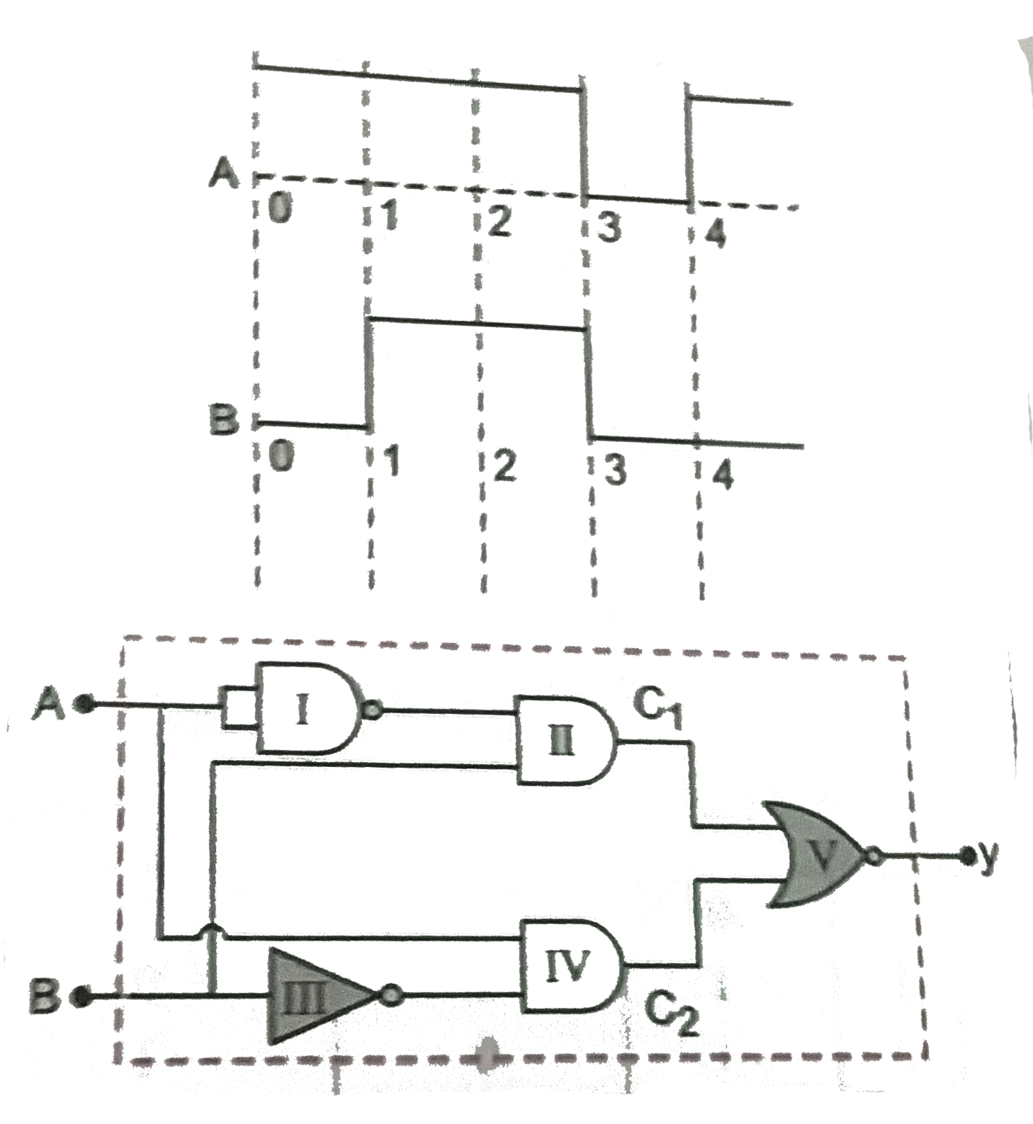
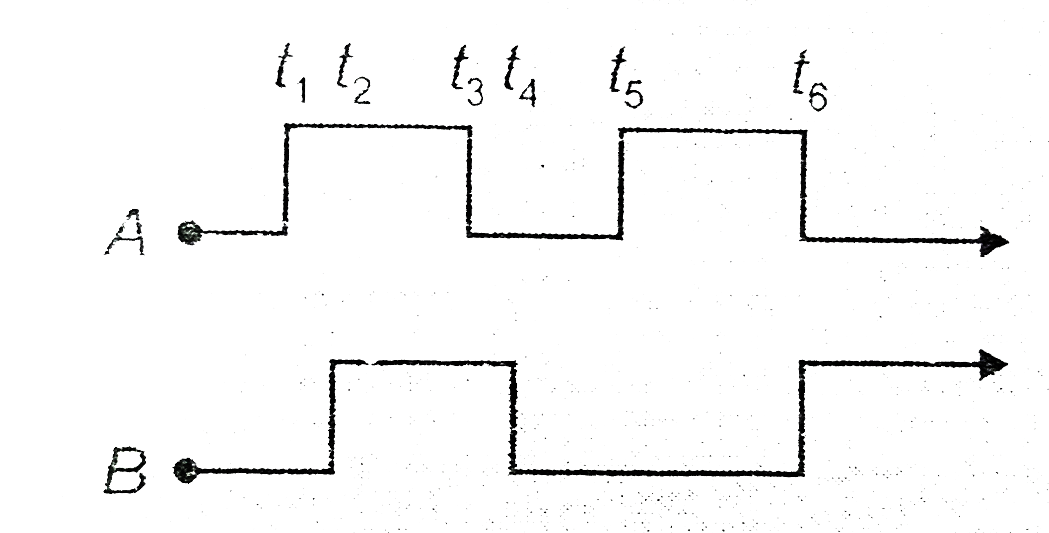
Input signal A and B are applied to the input terminals of the 'dotted box' set up shown here. Ley y be the final output signal from the box. What are the wavefroms of the signal labelled as C1 and C2 within the box giving (in brief) the reasons for getting these wave forms. Hence draw the waveform of the final output signal y. Give reasons for your choice. Write the relation between the total output y and the input signals A and B?
Video Solution
Text Solution
Here gate I is NAND gate working as NOT gate, gates II and IV and AND gates, gate III is NOT gate and V is NOR gate.
Boolean expression for C1=¯¯¯A.B
Boolean expression for C2=A.¯¯¯B
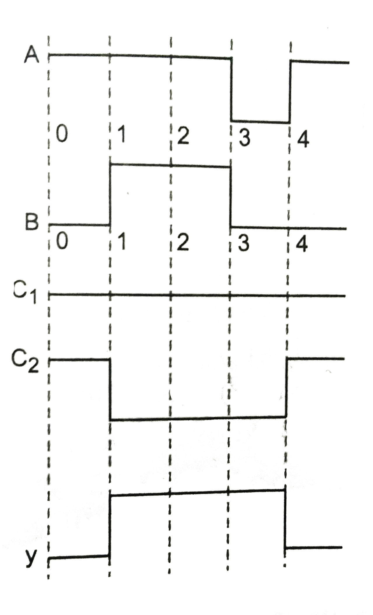
∴ Output y=¯¯¯¯¯¯¯¯¯¯¯¯¯¯C1+C2=¯¯¯¯¯¯¯¯¯¯¯¯¯¯¯¯¯¯¯¯¯A.B+A.¯¯¯B
Truth table of the circuit is given below (see ahead).
The wave forms C1,C2 and y are shown in Fig. below
∣∣
∣
∣
∣
∣
∣
∣
∣
∣
∣∣TimeAB¯¯¯A¯¯¯BC1=C2=y=interval¯¯¯A.BA.¯¯¯B¯¯¯¯¯¯¯¯¯¯¯¯¯¯C1+C2For0to11001010For1to21100001For2to31100001For3to40011001For more1001010than4∣∣
∣
∣
∣
∣
∣
∣
∣
∣
∣∣
|
Topper's Solved these Questions
- ELECTRONIC DEVICESBOOK - PRADEEPCHAPTER - ELECTRONIC DEVICESEXERCISE - LONG QUESTION ANSWER
2 Videos
- ELECTRONIC DEVICESBOOK - PRADEEPCHAPTER - ELECTRONIC DEVICESEXERCISE - PROBLEMS FOR PRACTICE
7 Videos
- ELECTRONIC DEVICESBOOK - PRADEEPCHAPTER - ELECTRONIC DEVICESEXERCISE - HIGHER ORDER THINKING SKILLS
1 Videos
- ELECTROMAGNETIC WAVESBOOK - PRADEEPCHAPTER - ELECTROMAGNETIC WAVESEXERCISE - II Focus multiple choice question
5 Videos
- ELECTROSTATICSBOOK - PRADEEPCHAPTER - ELECTROSTATICSEXERCISE - ASSERTION-REASON TYPE QUESTIONS
2 Videos
Similar Questions
Knowledge Check
In AND gate, the output Y is 1 when the inputs A and B are:
AA=1, B=0BA=1, B=1CA=0, B=0DA=0, B=1
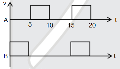
input are given as shown
then output signal is-A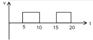 B
B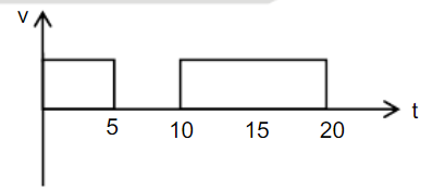 C
C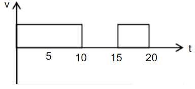 D
D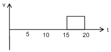
Which of the following figures correctly shows the phase relation between the input signal and the output signal of triode amplifier
A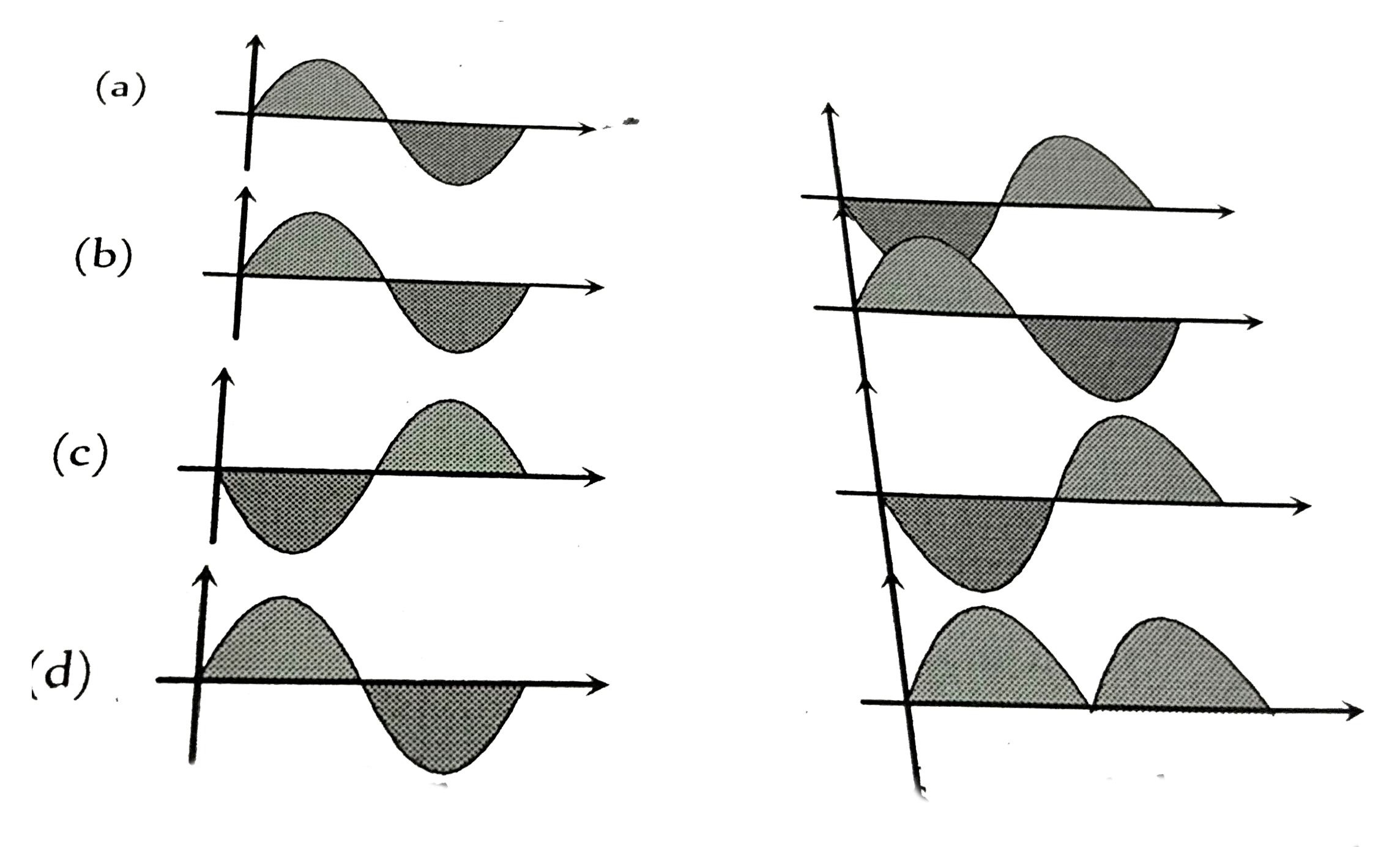 B
B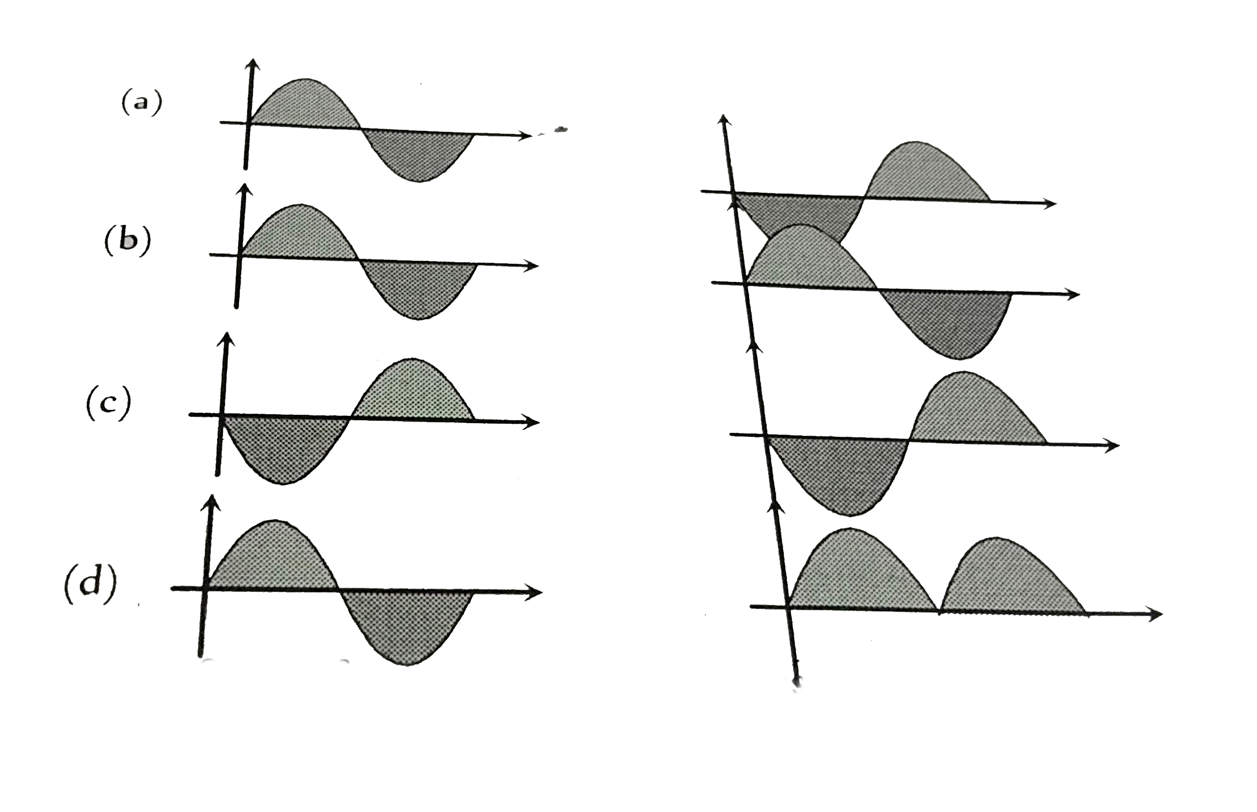 C
C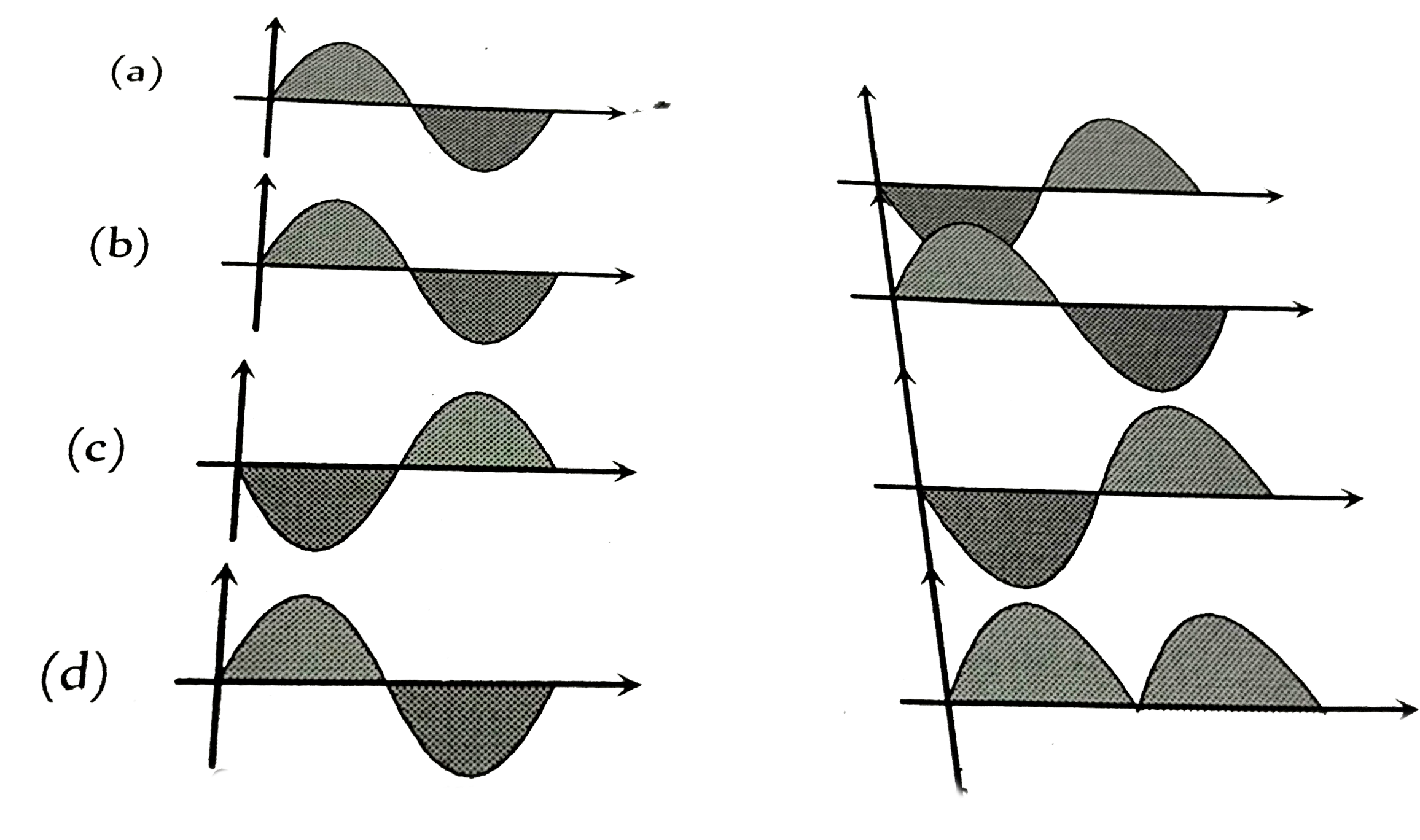 D
D
Write the output waveform of the OR gate for the inputs
View SolutionUsing the wave forms of the input A and B, draw the output waveform of the given logic circuit . Identify the logic gate obtained . Write also the truth table.

View SolutionShow the output waveform of OR gate for the following input waveforms of A and B
View SolutionShow the output waveform of OR gate for the following input waveforms of A and B

View SolutionIn a common emitter amplifier the input signal is applied across
View Solution

