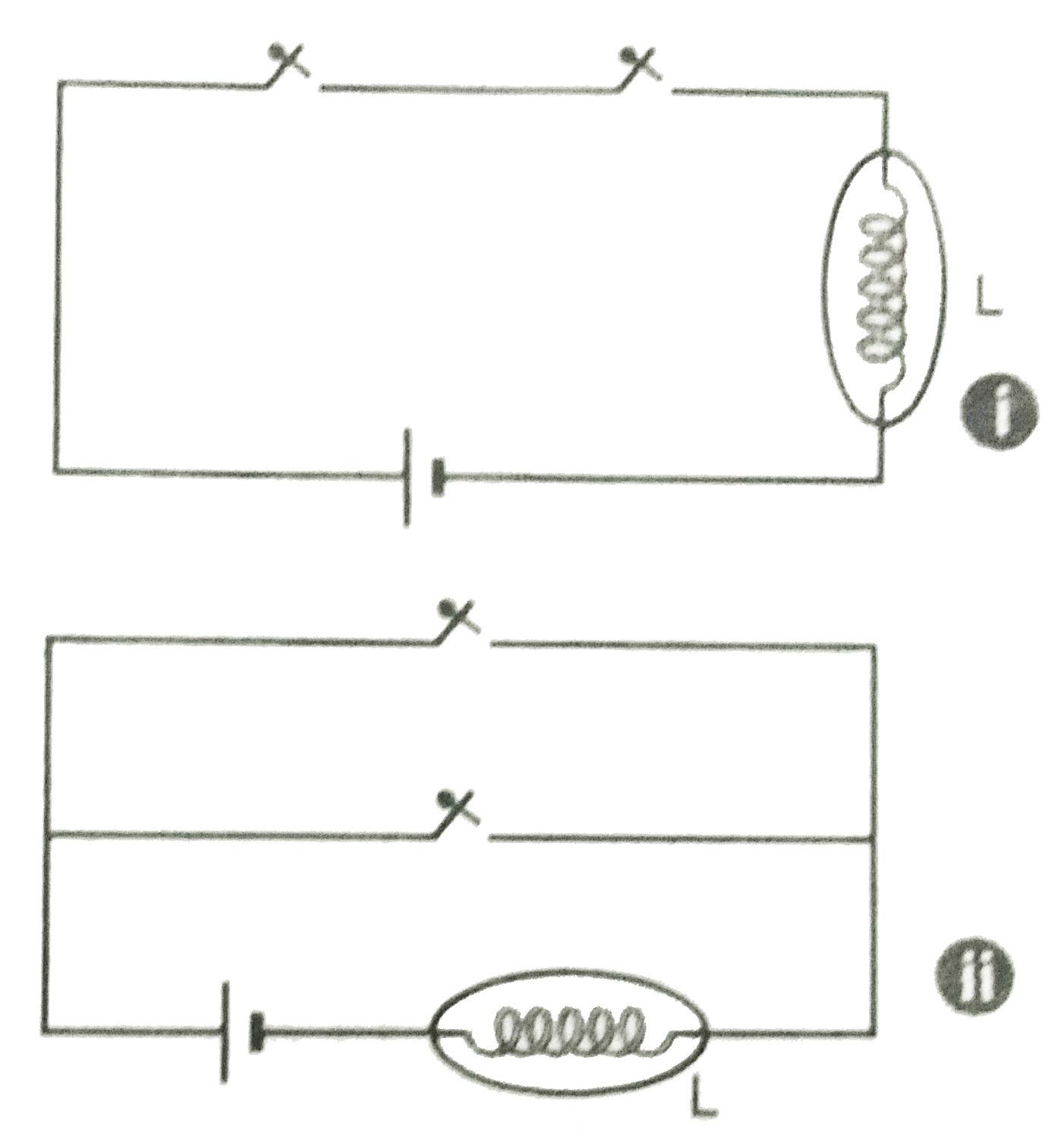
In the circuit shown , a switch which is open represents the logic state 0 and the switch which is closed represents the logic state 1. The lampL is lit when output is logic state 1. What type of gates are represented by the circuits in (i) and (ii) of Fig.
Video Solution
Text Solution
(i) AND gate (ii) OR gate
|
Topper's Solved these Questions
- ELECTRONIC DEVICESBook:PRADEEPChapter:ELECTRONIC DEVICESExercise:SAMPLE PROBLEM
Explore 2 Videos
- ELECTRONIC DEVICESBook:PRADEEPChapter:ELECTRONIC DEVICESExercise:CONCEPTUAL PROBLEMS
Explore 1 Video
- ELECTROMAGNETIC WAVESBook:PRADEEPChapter:ELECTROMAGNETIC WAVESExercise:II Focus multiple choice question
Explore 5 Videos
- ELECTROSTATICSBook:PRADEEPChapter:ELECTROSTATICSExercise:ASSERTION-REASON TYPE QUESTIONS
Explore 2 Videos
Similar Questions
Knowledge Check
In the circuit shown in the figure The steady state currents i1andi2 in the coils after the switch S is closed are
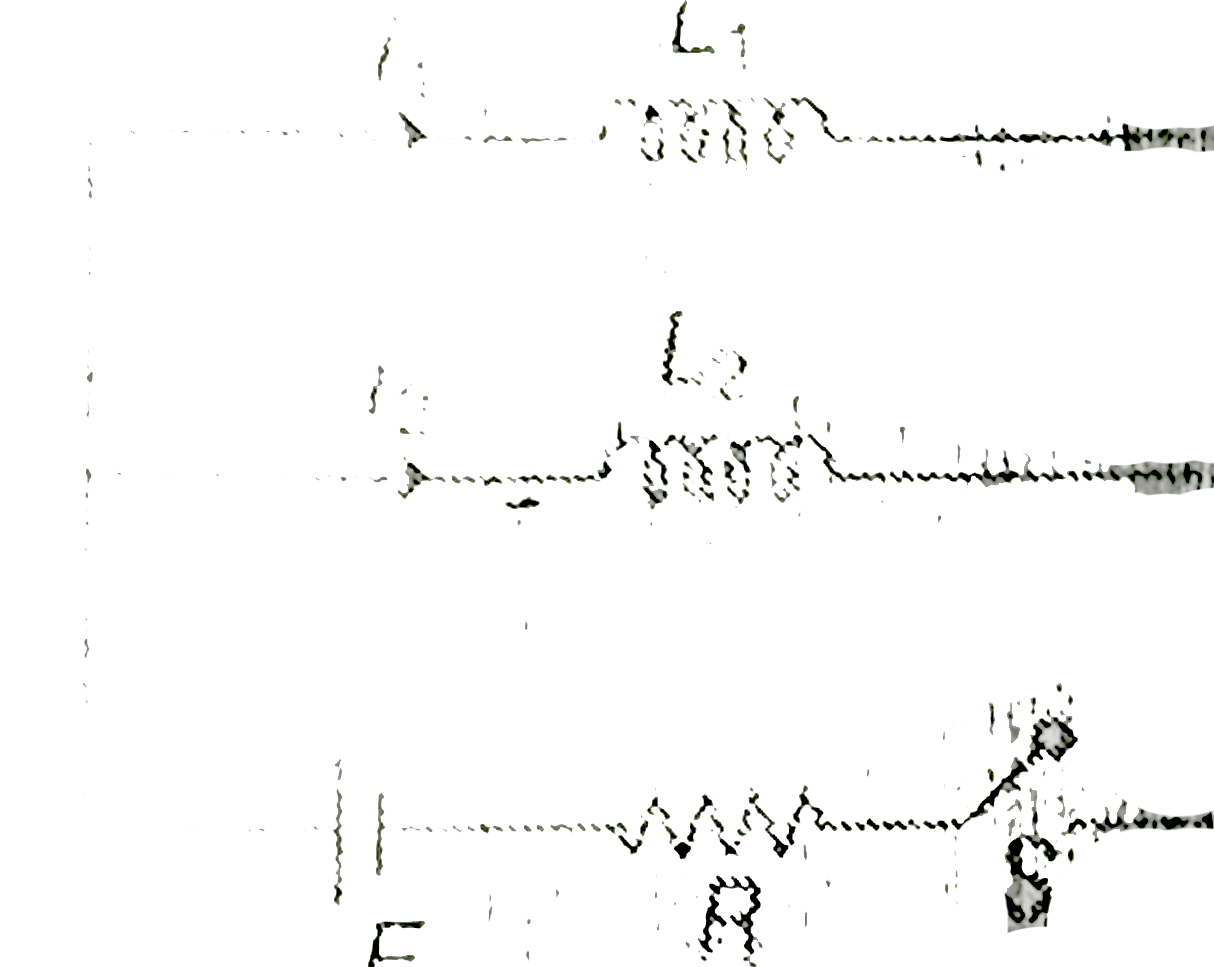 Ai1=EL2R(L1+L2)Bi1=EL1R(L1+L2)Ci2=EL2R(L1+L2)Di2=E√L1L2RL2
In the circuit shown, the switch is closed at t=0, the currents I1,I2 and I3 are
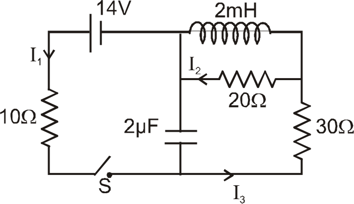 A1.4A,0,0B1.4 A,0.70 A,0.70 AC0,0,0D1.2A,0.6A,0.6A
The circuit given below represents which of the logic operations?
 ANOTBANDCORDNOR
Which logic gate is represented by the following truth table ?
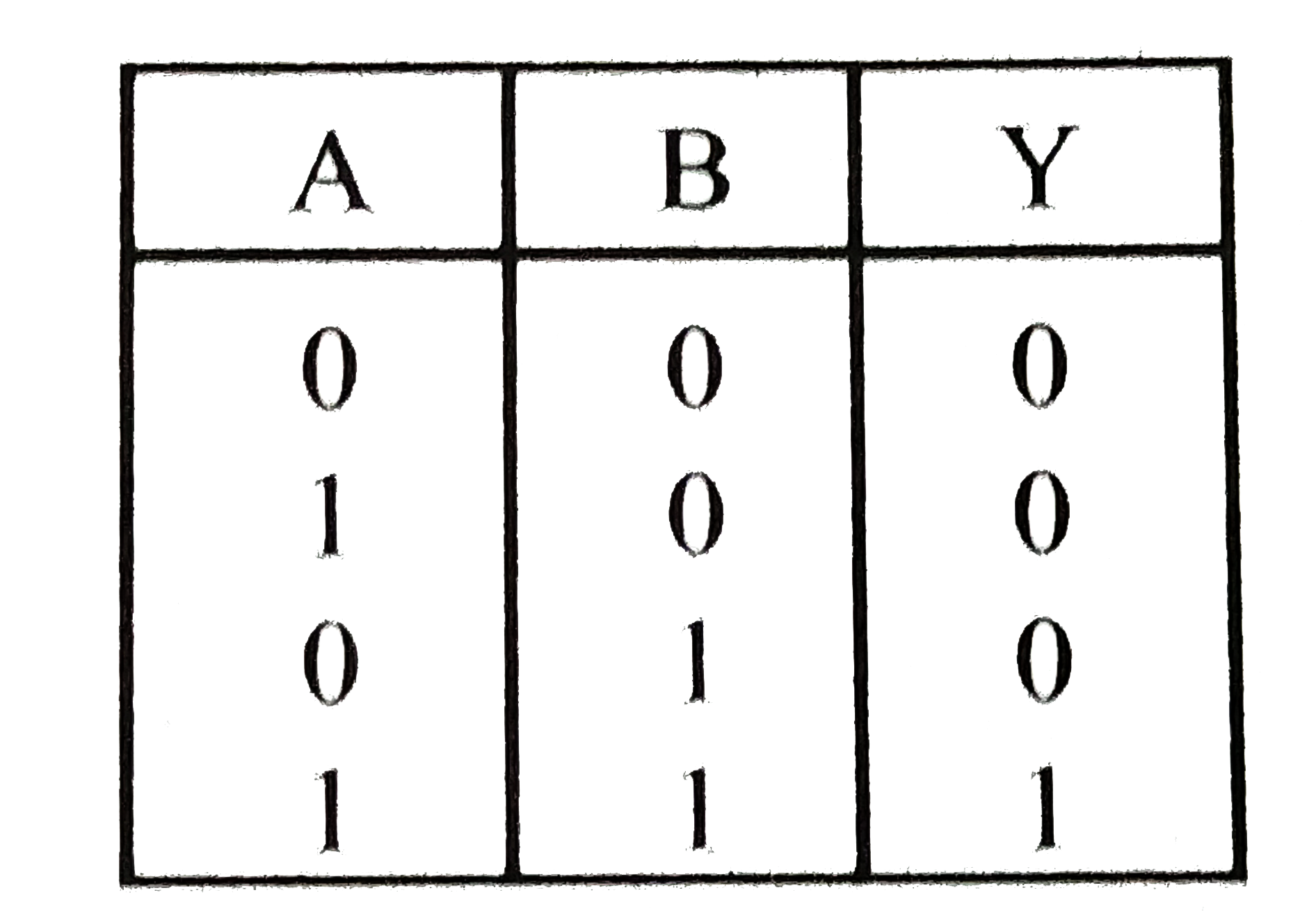
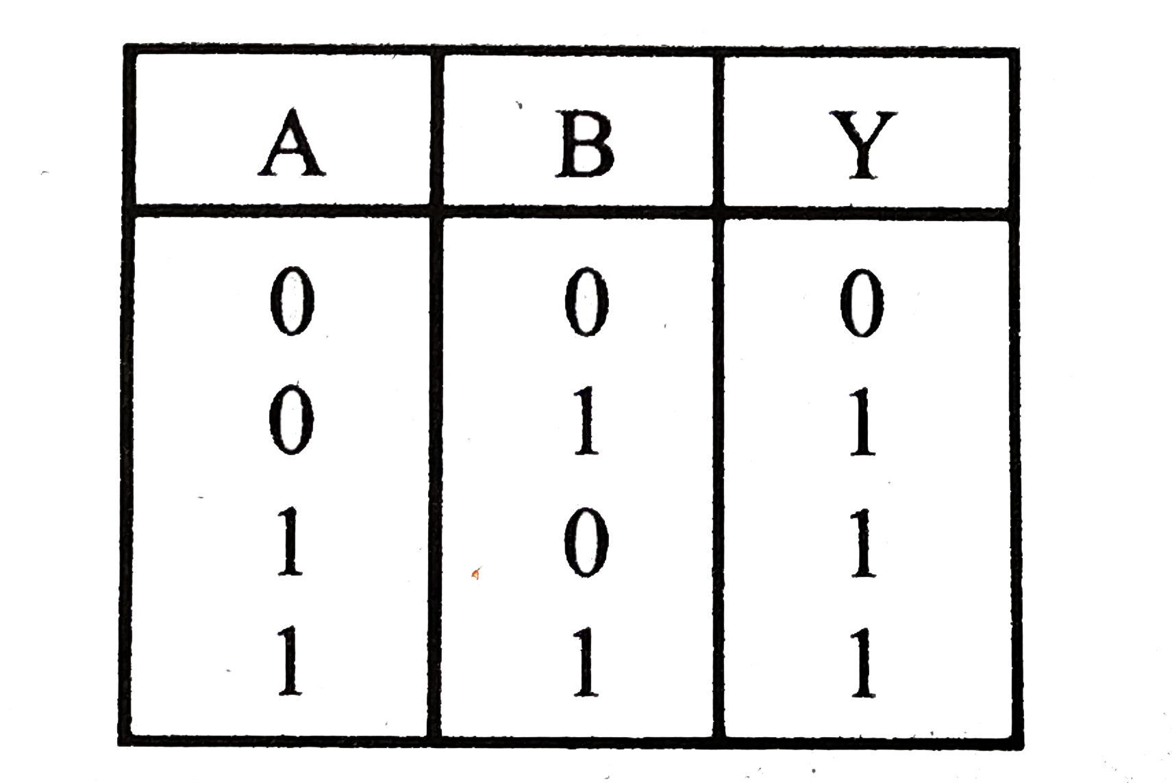
View SolutionWhich logic gate is represented by the following truth table?
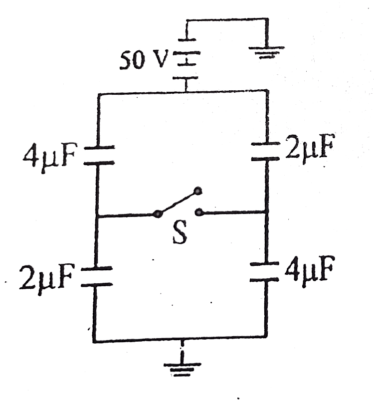
View SolutionThe circuit was in the shown state from a long time. Now the switch S is closed. The charged that flows through the switch is
View SolutionIn the circuit shown in figure initially the switch is opened. The switch is closed now.
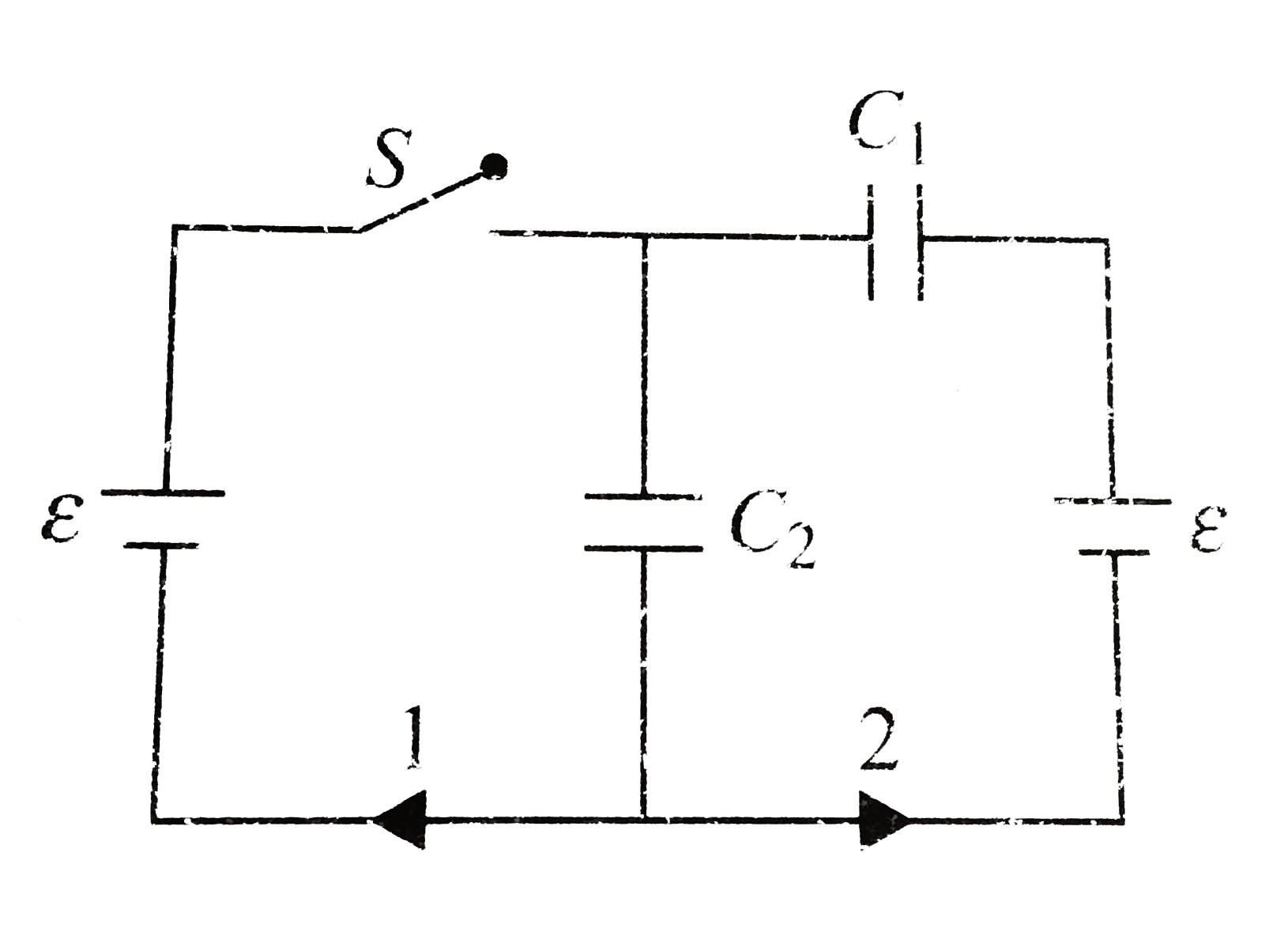
The charge that will flow in direction 1 is
View SolutionIn the circuit shown, the switch S has been close for a long time. At time t=0 the switch is opened. It remains open for a long time T, after which it is closed again.

View Solution


