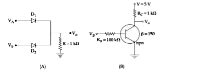
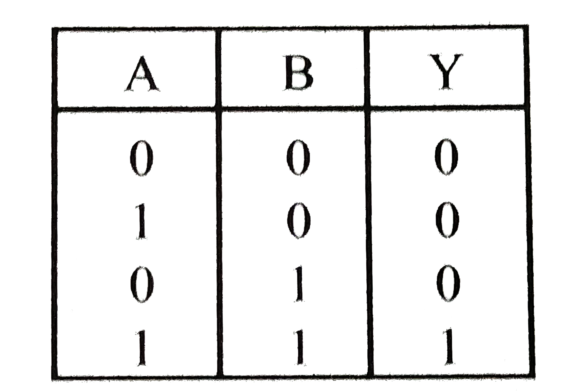
Name the Gate represented by the following circuit.

A
OR gate
B
XOR gate
C
AND gate
D
HAND gate
Video Solution
Text Solution
The correct Answer is:B
Output of OR gate is A+B. Output of NAND gate is ¯¯¯A.¯¯¯B.
New, Y=(A+B).¯¯¯¯¯¯¯¯A.B=(A+B).(¯¯¯A+¯¯¯B)
If A=1 and B=1 then
A+B=1
and ¯¯¯A+¯¯¯B=0
So, Y=0
If A=0 and B=0, then Y=0
If A=1 and B=0, then
A+B gives 1¯¯¯A+¯¯¯B=1 gives
So, Y=1
If A=1 and B=1, then
Y=1 So, the given combination is XOR gate
|
Topper's Solved these Questions
- SEMICONDUCTOR ELECTRONICSBOOK - A2ZCHAPTER - SEMICONDUCTOR ELECTRONICSEXERCISE - Problems Based On Mixed Concepts
32 Videos
- SEMICONDUCTOR ELECTRONICSBOOK - A2ZCHAPTER - SEMICONDUCTOR ELECTRONICSEXERCISE - Section B - Assertion Reasoning
22 Videos
- SEMICONDUCTOR ELECTRONICSBOOK - A2ZCHAPTER - SEMICONDUCTOR ELECTRONICSEXERCISE - Junction Transistor
47 Videos
- NUCLEAR PHYSICSBOOK - A2ZCHAPTER - NUCLEAR PHYSICSEXERCISE - Section D - Chapter End Test
29 Videos
- SOURCE AND EFFECT OF MAGNETIC FIELDBOOK - A2ZCHAPTER - SOURCE AND EFFECT OF MAGNETIC FIELDEXERCISE - Section D - Chapter End Test
30 Videos
Similar Questions
Knowledge Check
Which logic gate is represented by the following combination of logic gates
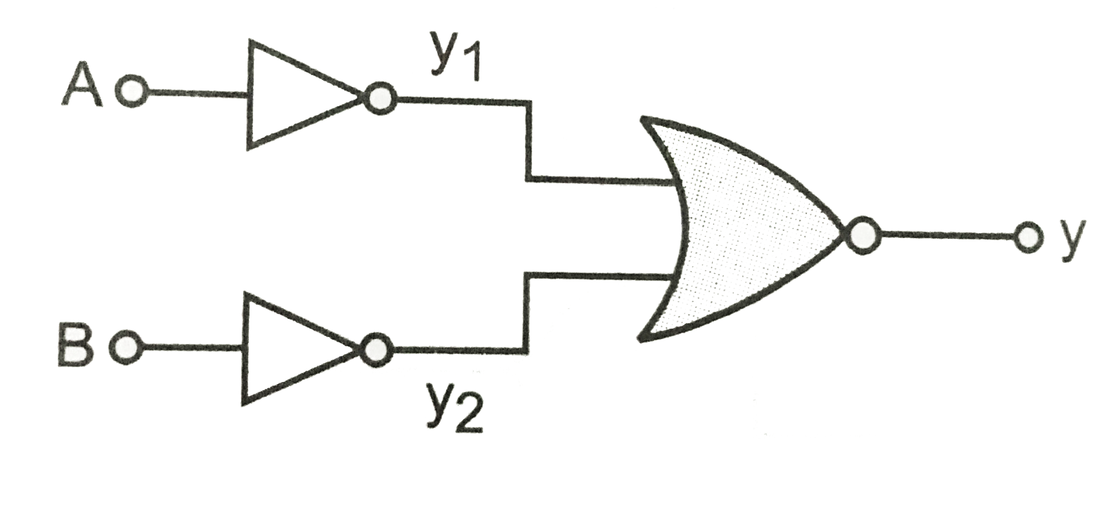 ANANDBANDCNORDOR
Which logic gate is represented by the following combination of logic gates
 AORBNANDCANDDNOR
Which logic gate is represented by the following combination of logic gates ?
 AORBNANDCANDDNOR
Which logic gate is represented by the following truth table?
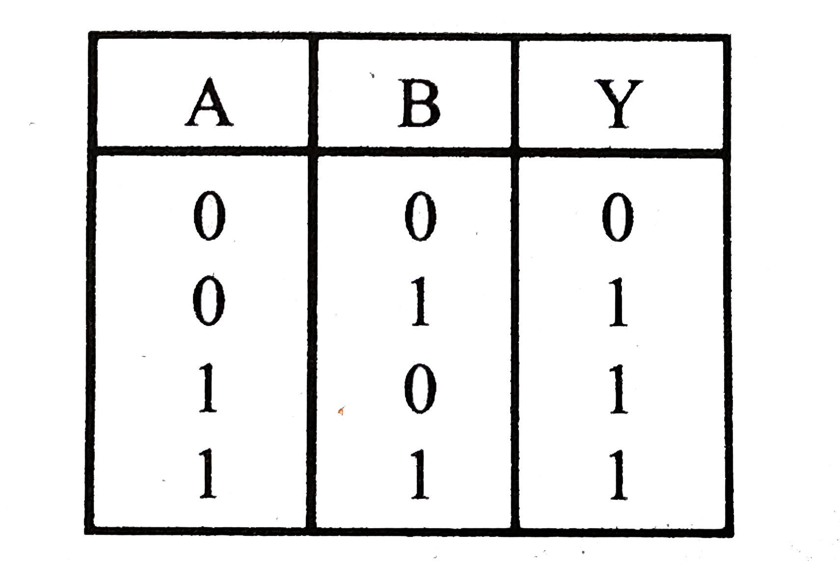
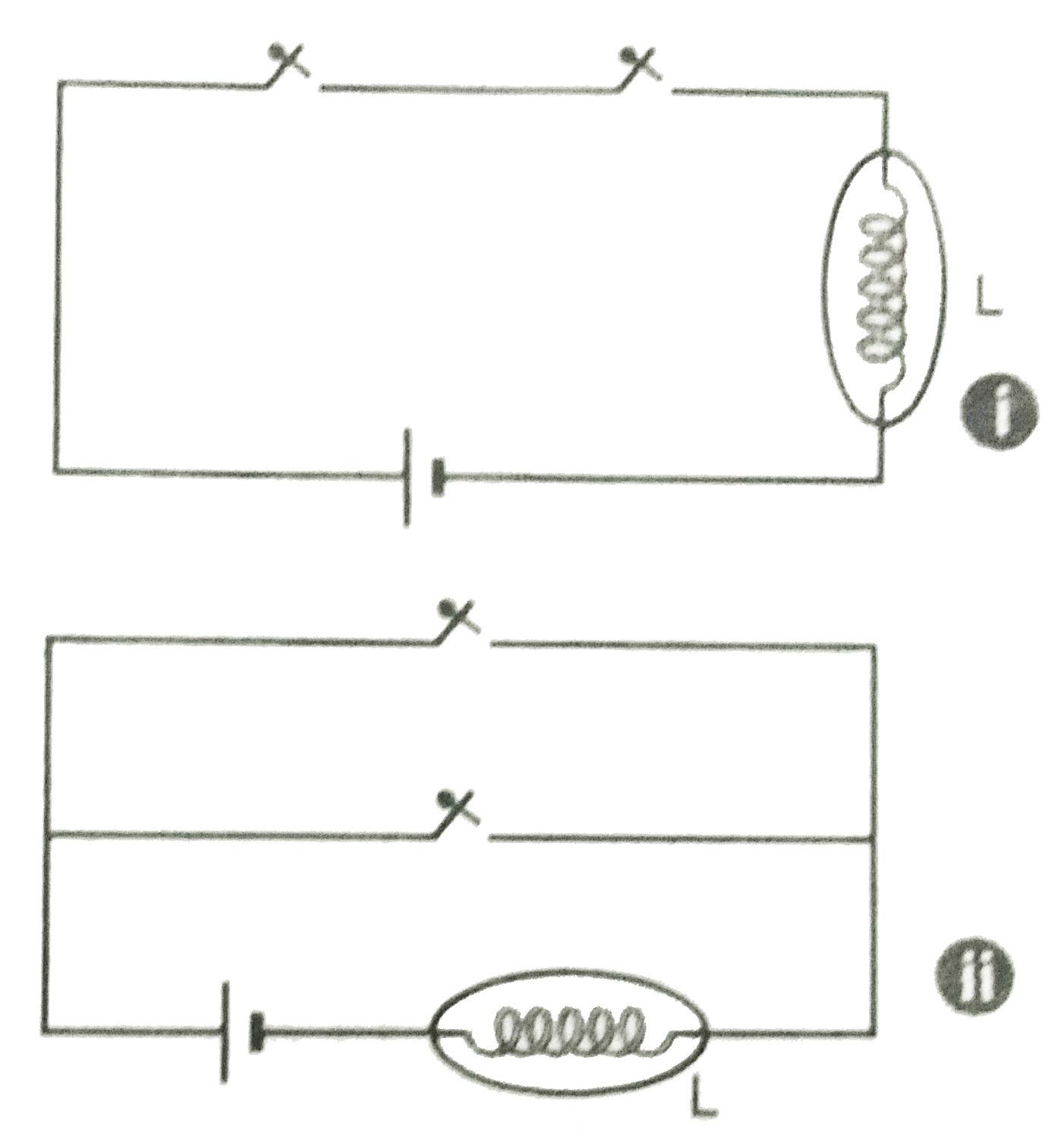
View SolutionIn the circuit shown , a switch which is open represents the logic state 0 and the switch which is closed represents the logic state 1. The lampL is lit when output is logic state 1. What type of gates are represented by the circuits in (i) and (ii) of Fig.
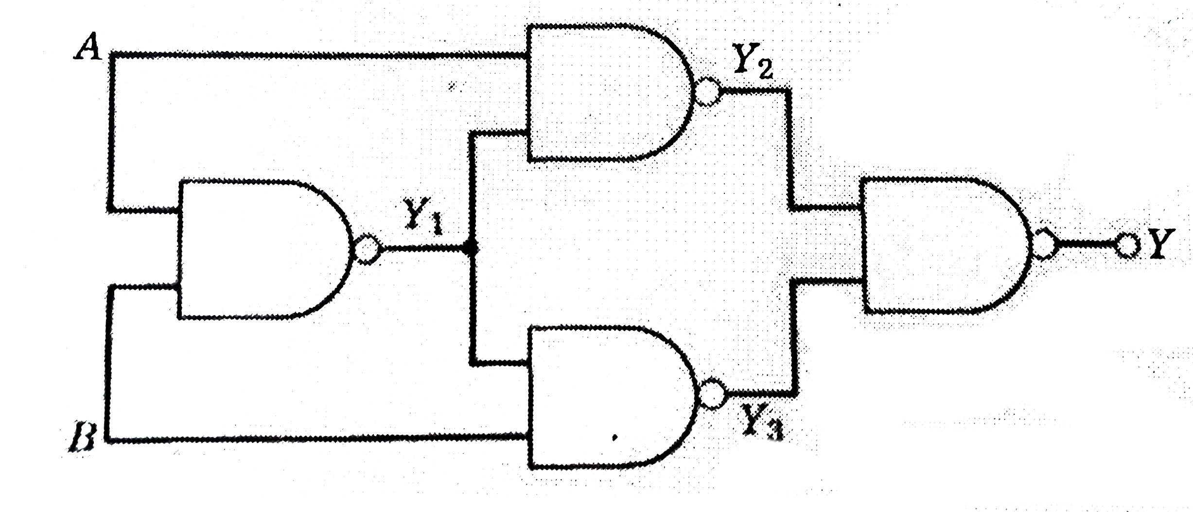
View SolutionWrite the truth table for the following circuit? Give the name of the resulting gate.
View Solution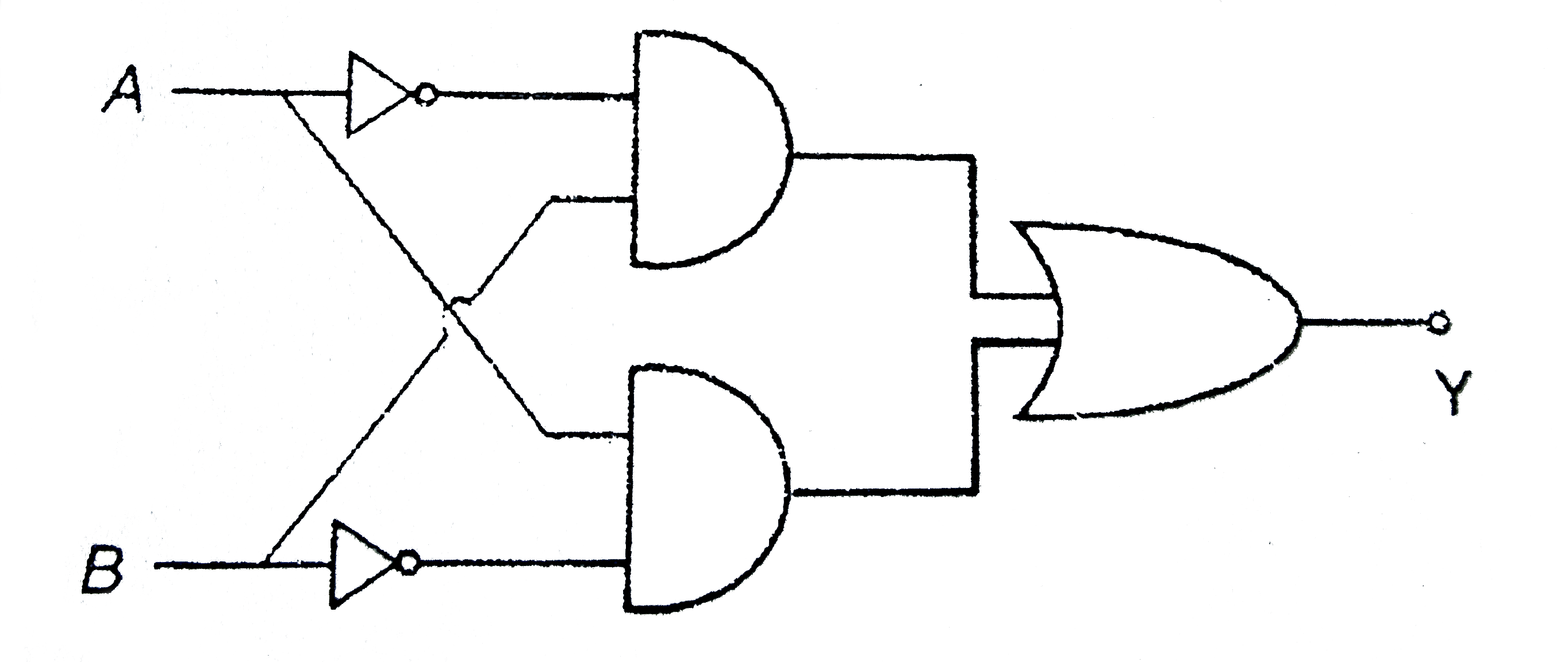
The following circuit represents:
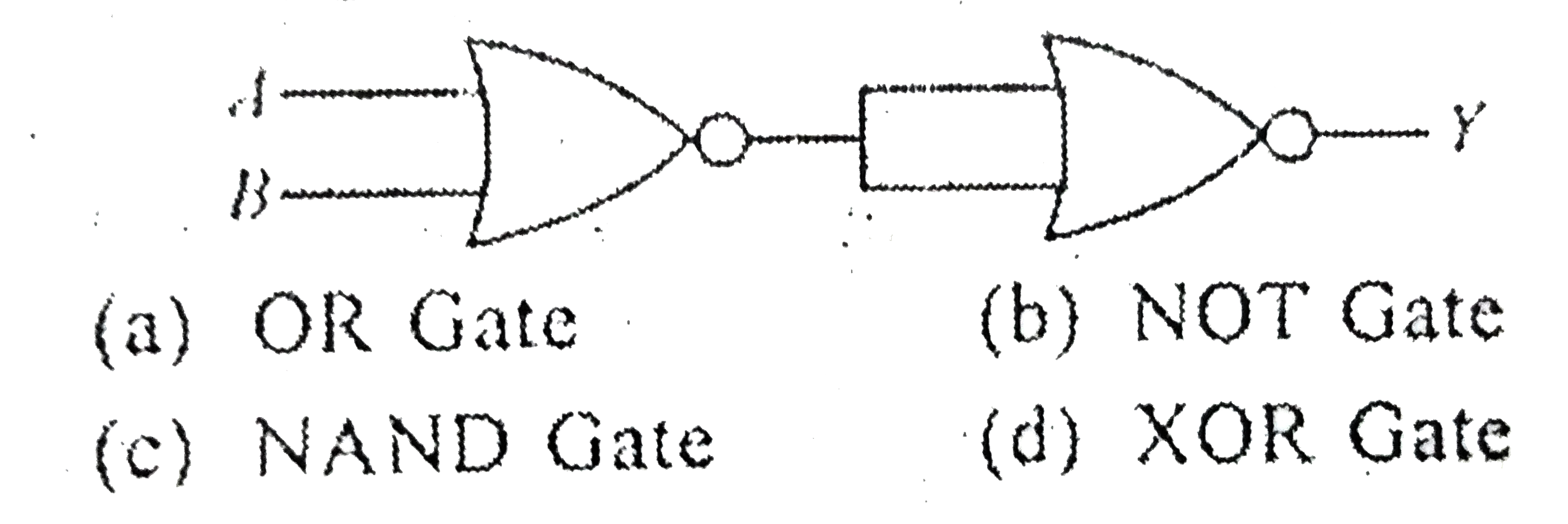
View SolutionThe logic gate represented in following figure is
View Solution

