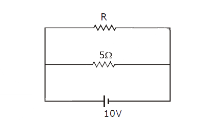
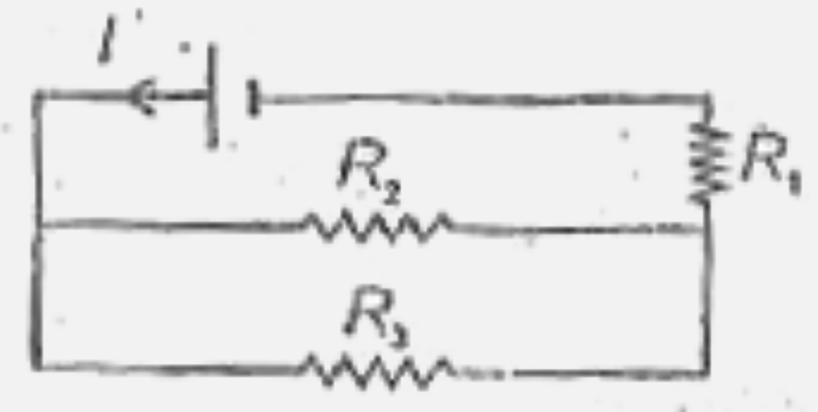
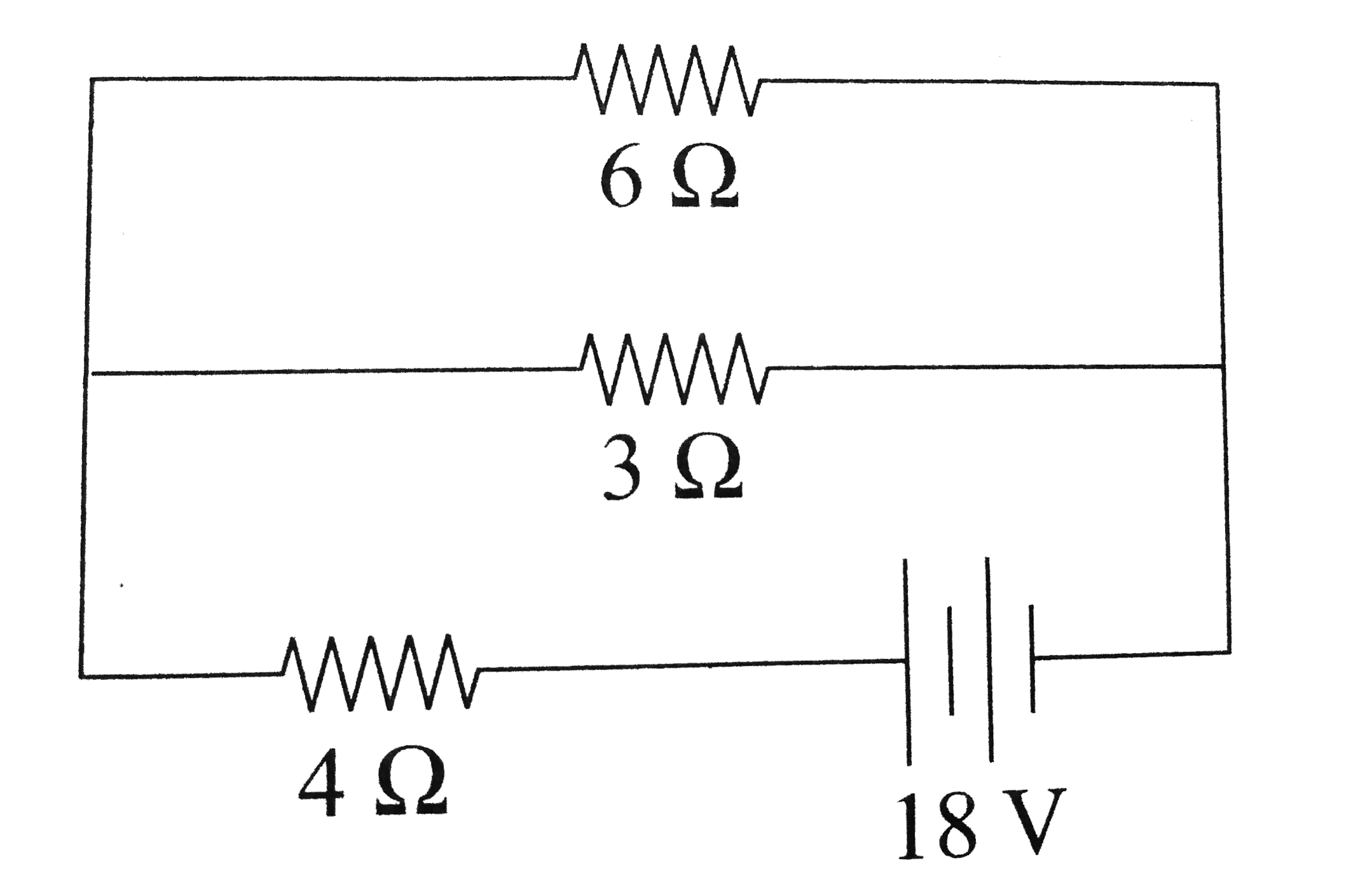
The total power dissipated in watts in the circuit shown here is
A
16
B
40
C
54
D
4
Video Solution
Text Solution
The correct Answer is:C
(c ) The resistance of 6Ω and 3Ω are in parallel in the given circuit, their equivalent resistance is
1R1=16+13=1+26=12
or R1=2Ω
Again, R1 is in series with 4Ω resistance, hence ltbgt R=R1+4=2+4=6Ω
Thus, the total power dissipatesin the circuit
P=V2R
Here, V=18V,R=6Ω
Thus, P=(18)26=54W
|
Topper's Solved these Questions
- CURRENT ELECTRICITYBook:A2ZChapter:CURRENT ELECTRICITYExercise:Section - C
Explore 1 Video
- CURRENT ELECTRICITYBook:A2ZChapter:CURRENT ELECTRICITYExercise:AIIMS Questions
Explore 36 Videos
- CURRENT ELECTRICITYBook:A2ZChapter:CURRENT ELECTRICITYExercise:Section B - Assertion Reasoning
Explore 28 Videos
- ATOMIC PHYSICSBook:A2ZChapter:ATOMIC PHYSICSExercise:Section D - Chapter End Test
Explore 30 Videos
- DUAL NATURE OF RADIATION AND MATTERBook:A2ZChapter:DUAL NATURE OF RADIATION AND MATTERExercise:Section D - Chapter End Test
Explore 30 Videos
Similar Questions
Knowledge Check
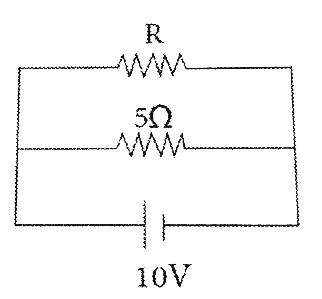
The power dissipated in the circuit shown in the figure is 30 watt. The shown in figure is 30 watt. The value of R is
 A20ΩB15ΩC10ΩD30Ω
The power dissipated in the circuit shown in the is 30 watts. The value of R is
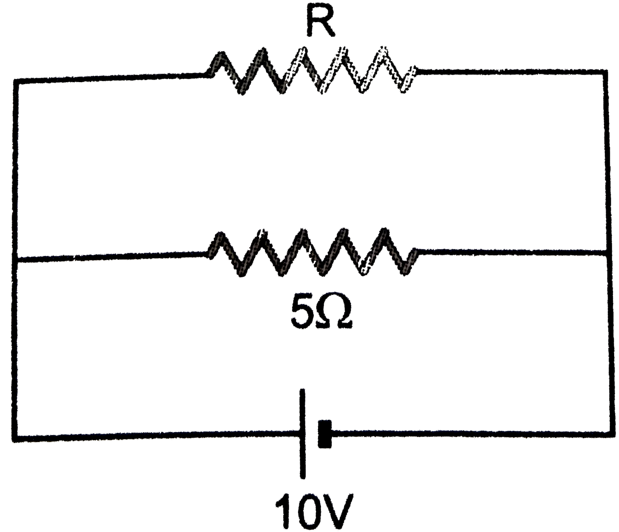 A20ΩB15ΩC10ΩD30Ω
Power dissipated across the 8Ω in the circuit shown here is 2W. The power dissiated in watt units across the 3Ω is
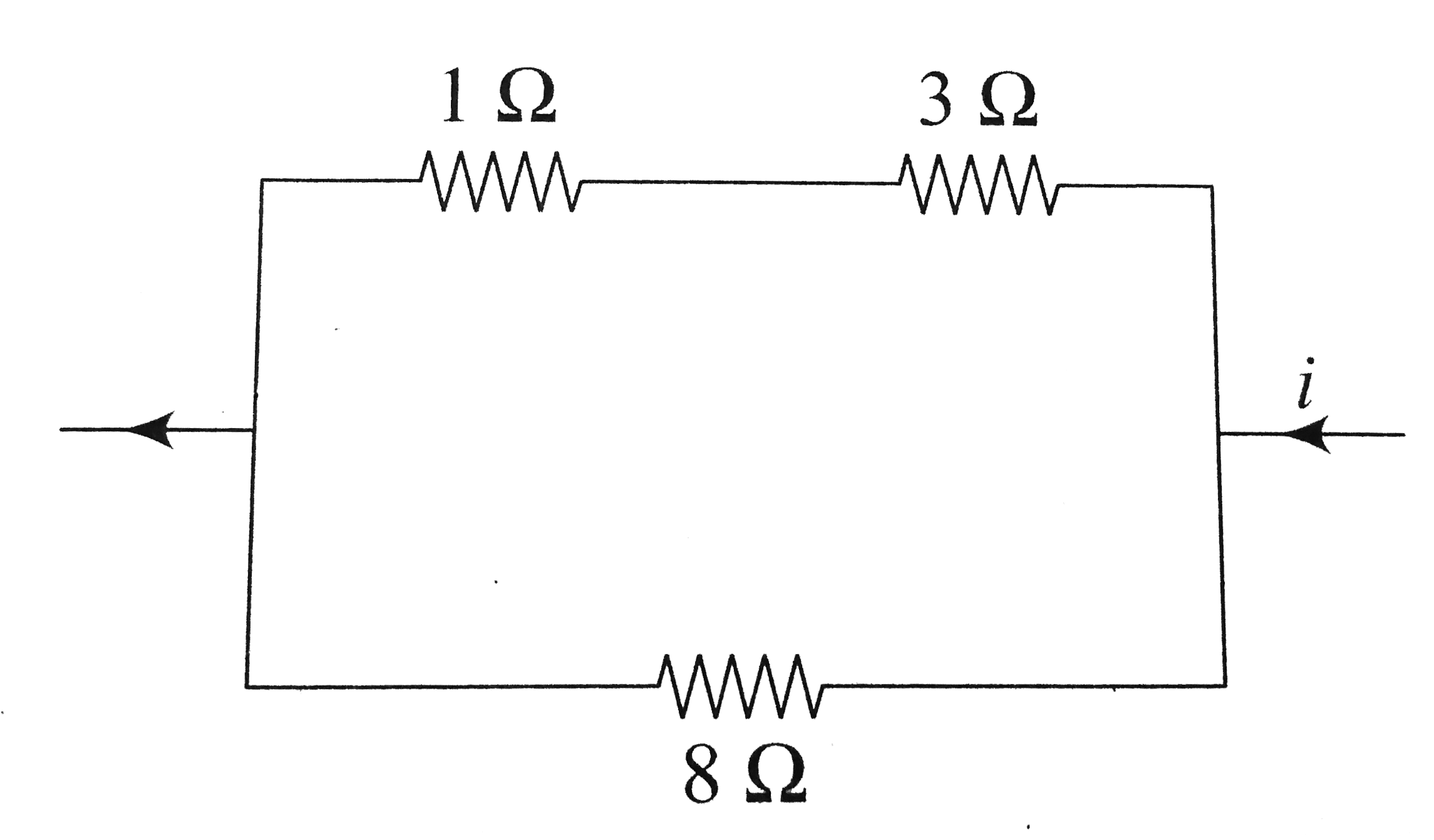 A2B1C0.5D3
The power dissipated in the following circuit is
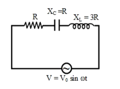
View SolutionThe power dissipated in the adjacent circuit is -
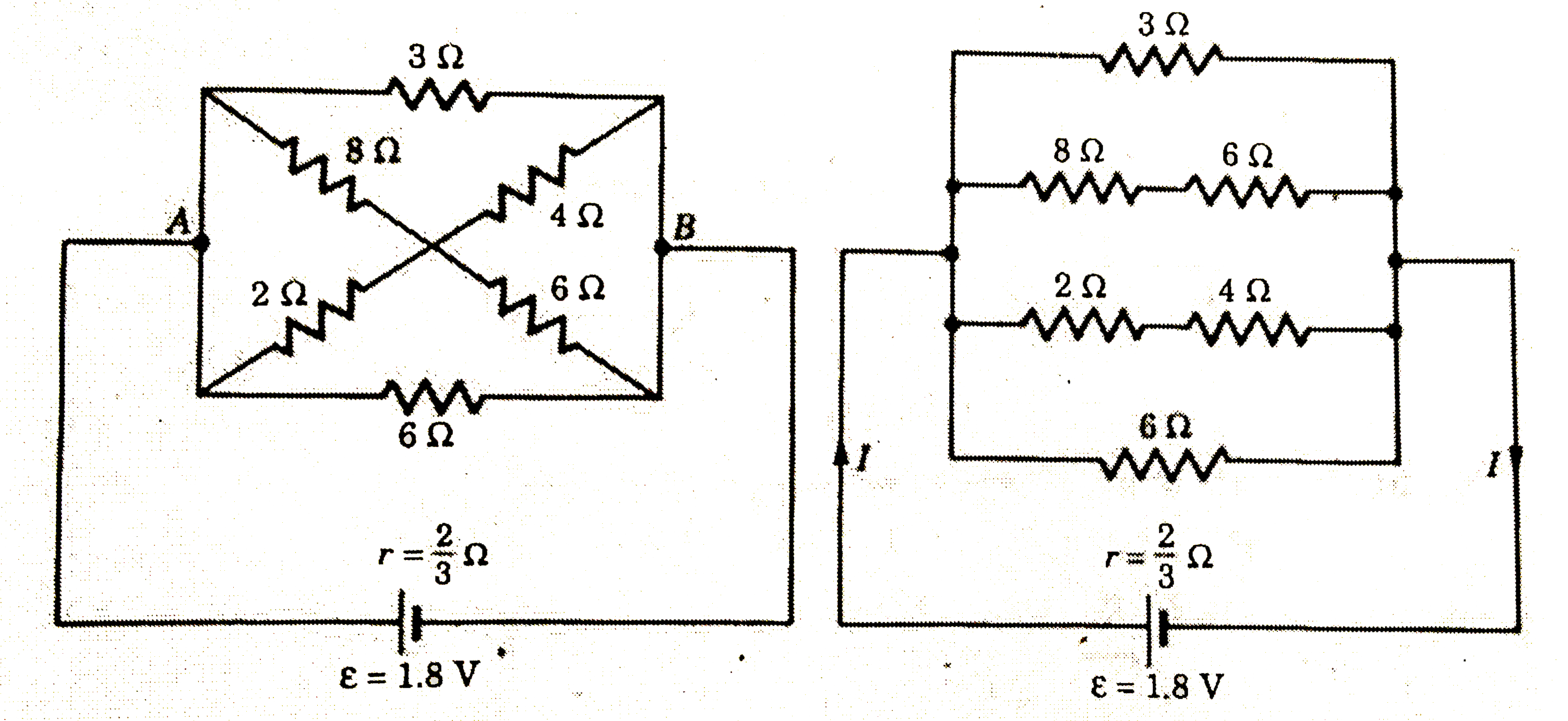
View SolutionCalculate the current in the 3Ω resistor and the power dissipated in the entire circuit shown in Fig. 6.10.
View SolutionThree 200Ω resistors are connected as shown in figure. The maximum power that can be dissipated in any one of the resistor is 50 W. Find the total power in watts dissipated in the circuit for maximum voltage across the terminals A and B.

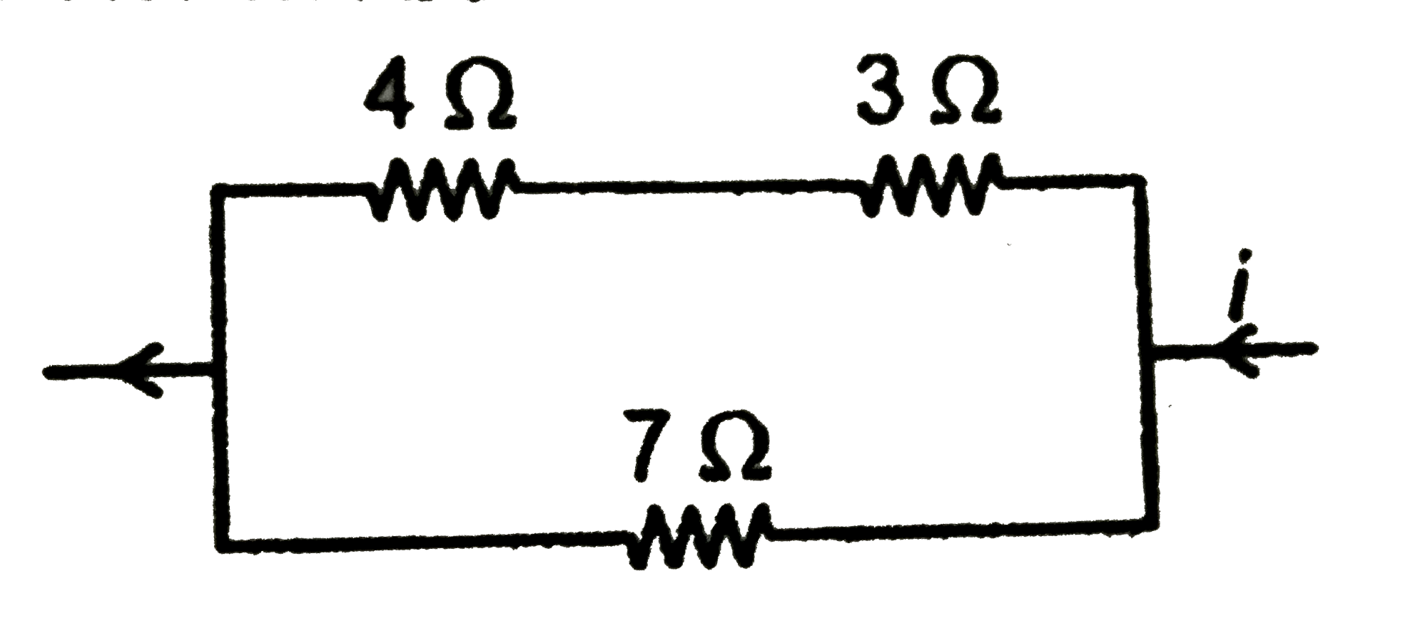
View SolutionThe power dissipated in 3Ω resistor in the circuits as shown in the figure is 2W. The power dissipated in 7Ω resistor will be
View Solution


