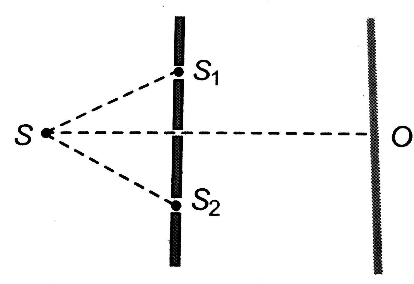
In YDSE arrangement as shown in figure, fringes are seen on screen using monochromatic source S having wavelength 3000 Å (in air). S1and S2 are two slits seperated by d = 1 mm and D = 1m. Left of slits S1 and S2 medium of refractive index n1=2 is present and to the right of S1 and S2 medium of n2=32, is present. A thin slab of thickness 't' is placed in front of S1 . The refractive index of n3 of the slab varies with distance from it's starting face as shown in figure.
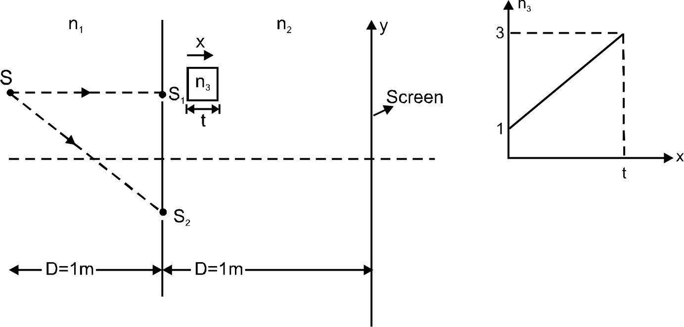
In order to get central maxima at the centre of screen, the thickness of slab required is :
1μm
2μm
0.5μm
1.5μm
Path difference
Δx=n1SS2+n2S2P−[(n1SS1+n2S1P)−∫t0(n3−n2)dx]
=n1(SS2−SS1)+n2(S2P−S1P)−∫t0n3dx+n_(2)t
In order to get central maxima at centre of screen
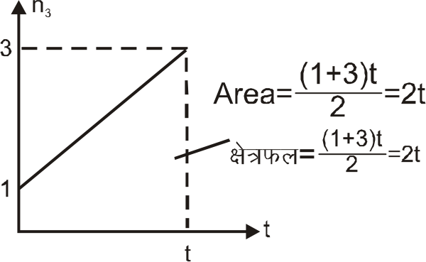
O=2×(1×10−3)22×1+0−2t+3t2
0.5t=1μm
t=2μm
Topper's Solved these Questions
Similar Questions
Knowledge Check
In YDSE arrangement as shown in figure, fringes are seen on screen using monochromatic source S having wavelength 3000 Å (in air). S1and S2 are two slits seperated by d = 1 mm and D = 1m. Left of slits S1 and S2 medium of refractive index n1=2 is present and to the right of S1 and S2 medium of n2=32, is present. A thin slab of thickness 't' is placed in front of S1 . The refractive index of n3 of the slab varies with distance from it's starting face as shown in figure.

Fringe width on the screen isA0.4 mmB0.1 mmC0.2 mmD0.3 mmIn YDSE arrangement as shown in figure, fringes are seen on screen using monochromatic source S having wavelength 3000 Å (in air). S1and S2 are two slits seperated by d = 1 mm and D = 1m. Left of slits S1 and S2 medium of refractive index n1=2 is present and to the right of S1 and S2 medium of n2=32, is present. A thin slab of thickness 't' is placed in front of S1 . The refractive index of n3 of the slab varies with distance from it's starting face as shown in figure.
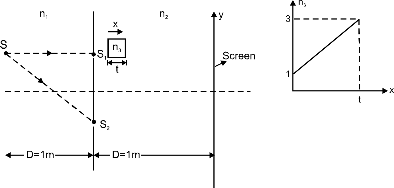
If thickness of the slab is selected 1μm, then position of central maxima will be : (y-coordinate)A1/3 mmB−13mmC1/6 mmD−16mmIn YDSE arangement shown in figure, fringes are seen on screen using monochromatic source S having wavelength 3000∘Δ (in air). S1 and S2 are two slits separate by d=1mm and D=1m . Left of slits S1andS2 medium of refractive index μ1=2 is presernt refractive index μ2=32 is present. A thin slab of thickness 't' is placed in front of S1 . The refractive index of slab μ3 varies with distance from its starting face as shown in figure.

If the thickness of the slab is selected 1μm , then the position of the central maxima will be (y - coordinate)A13mmB−13mmC16mmD−16mm
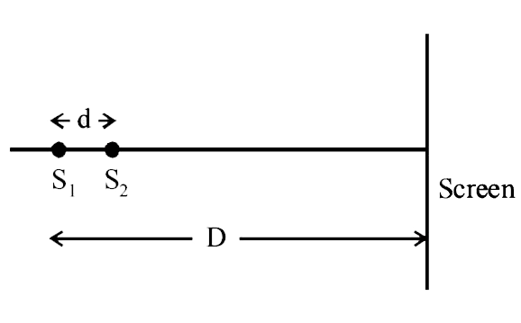
Two coherent point sources S1 and S2 are separated by a small distance d as shown. The fringes obtained on the screen will be
View Solution_S01_025_Q01.png)
In Young's double slit experiment the slits, S1&S2 are illuminated by a parallel beam of light of wavelength 4000 Å from the medium of refractive index n1=1.2 A thin film of thickness 1.2 μm and refractive index n=1.5 is placed infrom of S1 perpedicular to path of light. the refractive index of medium between plane of slits & screen is n2=1.4 if the light coming from the film and S1&S2 have equal intensities I then intensity at geometrical centre of the screen O is
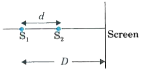
View SolutionTwo coherent point sources S1andS2 are separated by a small distance 'd' as shown. The fringes obtained on the screen will be :
View SolutionIn a Young's double-slit experiment set up, source S of wavelength 6000Å illuminates two slits S1 and S2 which act two coherent sources. The sources S oscillates about its shown position according to the eqation y=1+cosπt, where y is in millimeter and t in second.
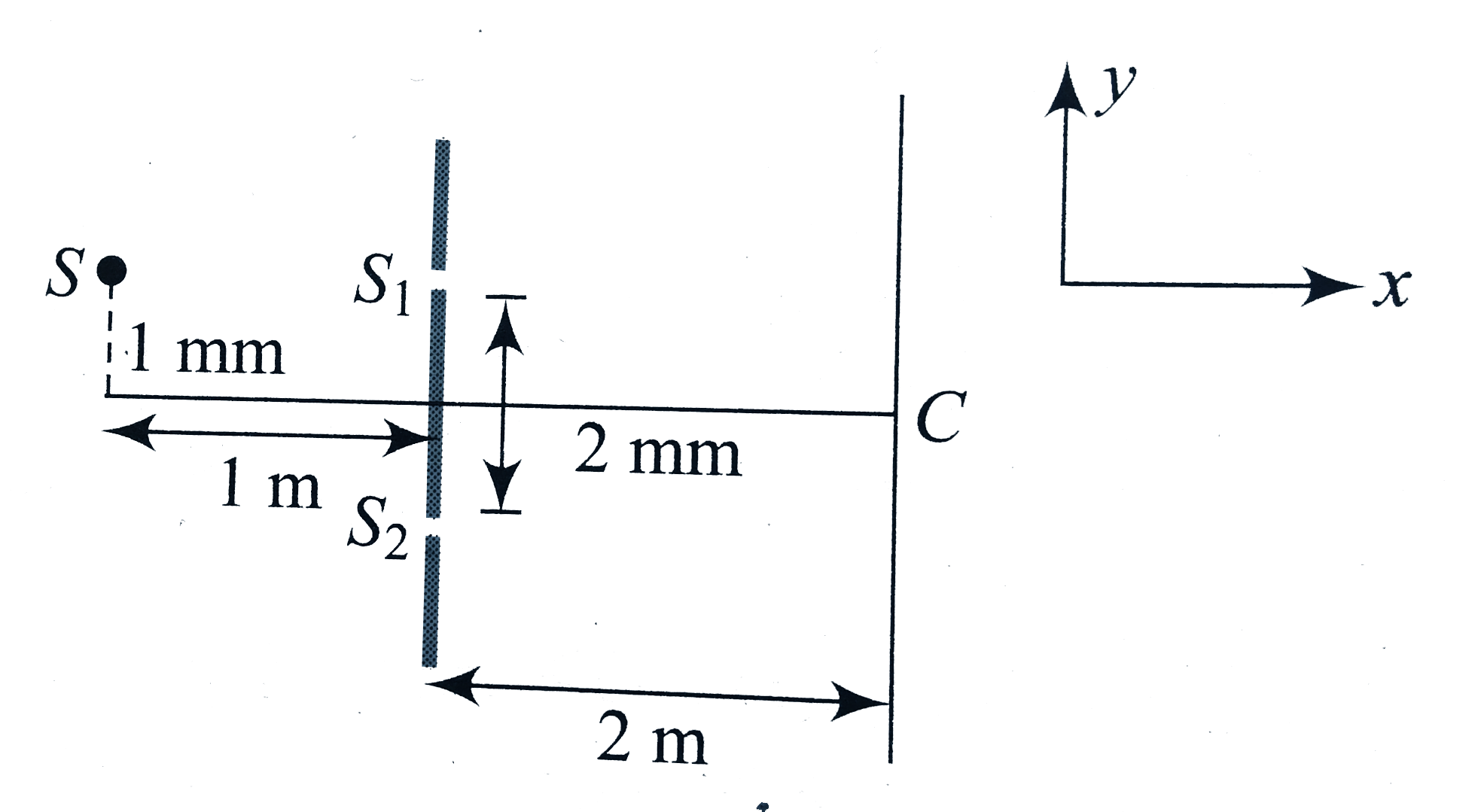
At t=1 s, a slab of thickness 2×10⁻³mm an refractive index 1.5 is placed just in front of S1. The central maximum is formed at
View SolutionFigure shows a YDSE setup having identical slits S1 and S2 with d =5 mm and D = 1 m. A monochromatic light of wavelength λ=6000Å is incident on the plane of slit due to which at screen centre O, an intensity I0 is produced with fringe pattern on both sides Now a thin transparent film of 11μm thickness and refractive index μ=2.1 is placed in front of slit S1 and now interference patten is observed again on screen.
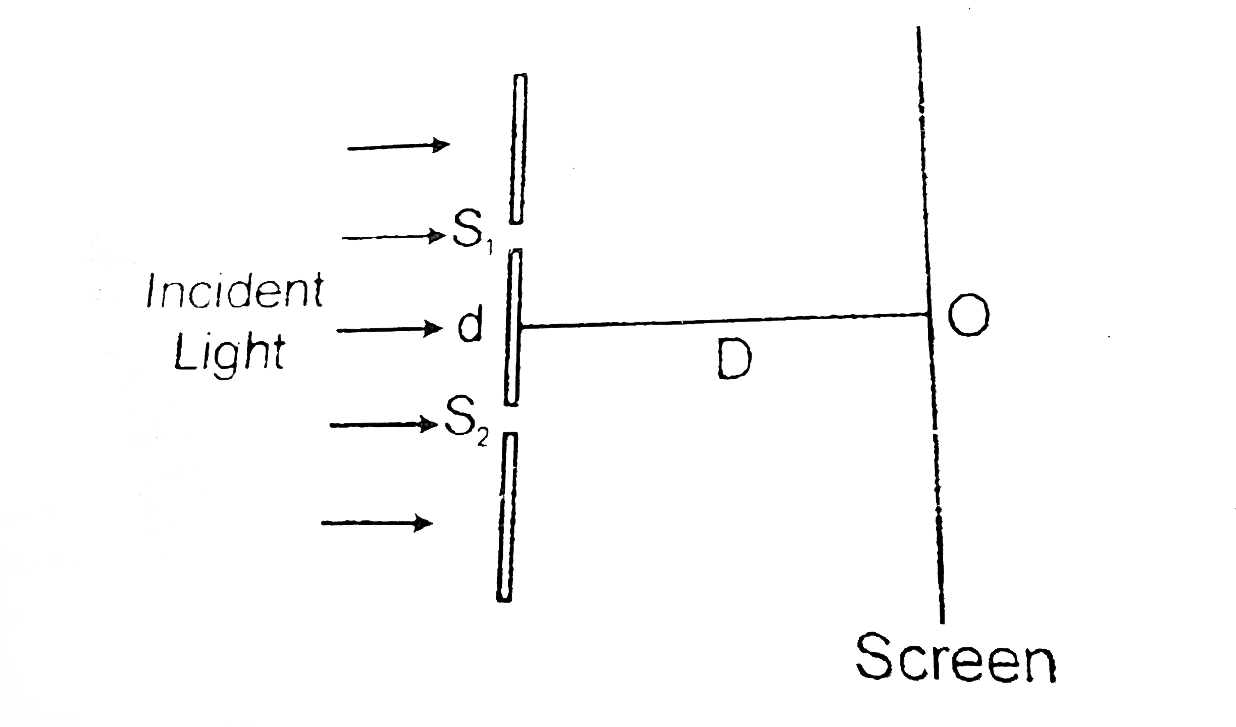
After placing the film of slit S1, the intensity at point O screen is :
View Solution


_PHY_E01_002_Q01.png)
