In the arrangement shown in figure, there are two coils wound on a non-conducting cylindrical rod. Initially the key is not inserted. Then the key is inserted and later removed. Then:
the deflection in the galvanometer remains zero throughout
there is a momentary deflection in the galvanometer but it dies out shortly and there is no effect when the key is removed
there are momentary galvanometer deflections that die out shortly, the deflections are in same direction
there are momentary galvanometer deflections that die out shortly, the deflections are in opposite directions
The correct Answer is:D
Step by step video, text & image solution for In the arrangement shown in figure, there are two coils wound on a non-conducting cylindrical rod. Initially the key is not inserted. Then the key is inserted and later removed. Then: by Physics experts to help you in doubts & scoring excellent marks in Class 10 exams.
Updated on:21/07/2023Topper's Solved these Questions
- MAGNETIC EFFECTS OF ELECTRIC CURRENTBook:PRADEEPChapter:MAGNETIC EFFECTS OF ELECTRIC CURRENTExercise:Mock Test
Explore 21 Videos
- MAGNETIC EFFECTS OF ELECTRIC CURRENTBook:PRADEEPChapter:MAGNETIC EFFECTS OF ELECTRIC CURRENTExercise:Value Based Questions
Explore 4 Videos
- ELECTRICITYBook:PRADEEPChapter:ELECTRICITYExercise:(Mock Test)Sec - B
Explore 6 Videos
- REFLECTION AND REFRACTIONBook:PRADEEPChapter:REFLECTION AND REFRACTIONExercise:NCERT EXEMPLAR PROBLEMS
Explore 19 Videos
Similar Questions
In the arrangement shown in figure, the rod of mass mhelp by two smooth walls, remains always perpendicular to the surface of the wedge of mass M. Assuumming all the surface to be frictionless, find the acceleration of the rod and that of the wedge.

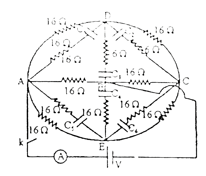
View SolutionThe resistance each of 16Ω and capacitance of each 100μF are arranged as shown in the figure. A battery of emf 12V is joined across A and B. Find the
(i) reading of the ammeter just after key is ciosed and after long time.
(ii) charges in each capacitors when steady state is achieved.
View Solution
Knowledge Check
Two rods of equal cross sections area are joined end the end as shown in figure. These are supported between two rigid vertical walls. Initially the rods are unstrained .
_E01_228_Q01.png)
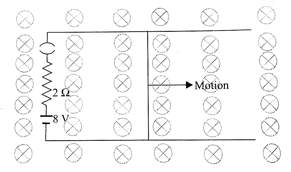
If temperature of system is increased by ΔT then thermal stress developed in first rod-Ais equal to thermal stress developed in second rodBis greater than thermal stress developed in second rodCis less than thermal stress developed in second rodDNone of theseFigure shows a conducting frame having battery and a resistance on which a movable conductor of length 0.5 m can slide, The whole arrangement is placed in a uniform magnetic field of B =0.4 T directed perpendicular and into the plane of frame. Initially the circuit is open. When the key is inserted, the conductor begins to move. It is found that a force 0.5 N has to be applied on the conductor to the left to keep it moving at constant speed to the right.
Current flowing in the conductor is:
 A5AB2.5 AC1.25 AD1A
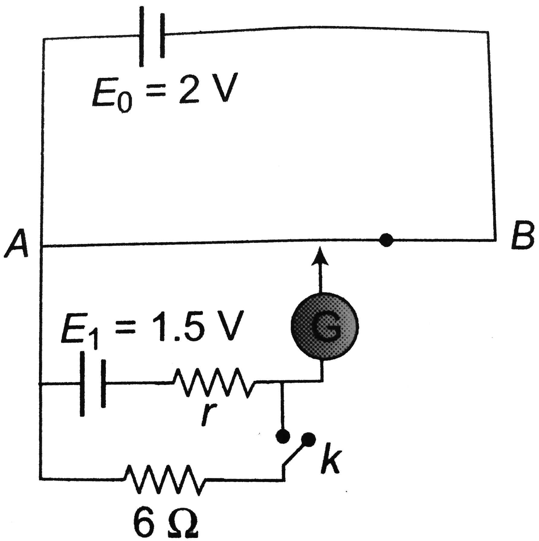
For the arrangement of the potentiometer shown in the figure, The balance point is obtained at a distance 75cm from A when the key k is open
The second balance point is obtained at 60cm from A when the key k is closed. Find the internal resistance of the battery E1.
 A1.5ΩB2ΩC0.5ΩD1Ω
In the arrangement shown in figure, the rod of mass m held by two smooth walls, remains always perpendicular to the surface of the wedge of mass M. Assuming all the surface to be frictionless, find the acceleration of the rod and that of the wedge.

View SolutionTwo rods of equal cross sections area are joined end the end as shown in figure. These are supported between two rigid vertical walls. Initially the rods are unstrained .
_E01_227_Q01.png)
If temperature of system is increased by ΔT then junction will not shift if -
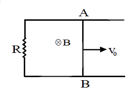
View SolutionTwo long parallel metallic wires with a resistance 'R' from a horizontal plane . A conducting rod AB is on the wires shown in figure . The space has magnetic field pointing vertically downwards. The rod is given an initial velocity 'v0'. There is no friction in the wire and the rod . After a time 't' the velocity v of the rod will be such that :-
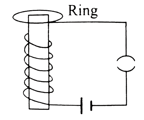
View SolutionFigure shows a powerful electromagnet arrangement. A copper ring, which is free to move, is placed on the projecting part of the core as shown.
When the key is inserted, the ring
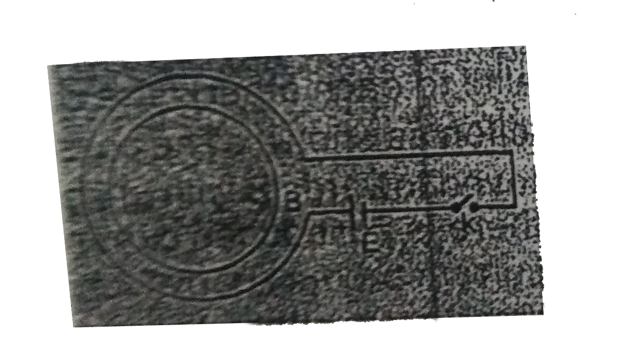
View SolutionAs shown in the figure, the key K is closed, the direction of the induced current in the coil B will be -
View Solution

