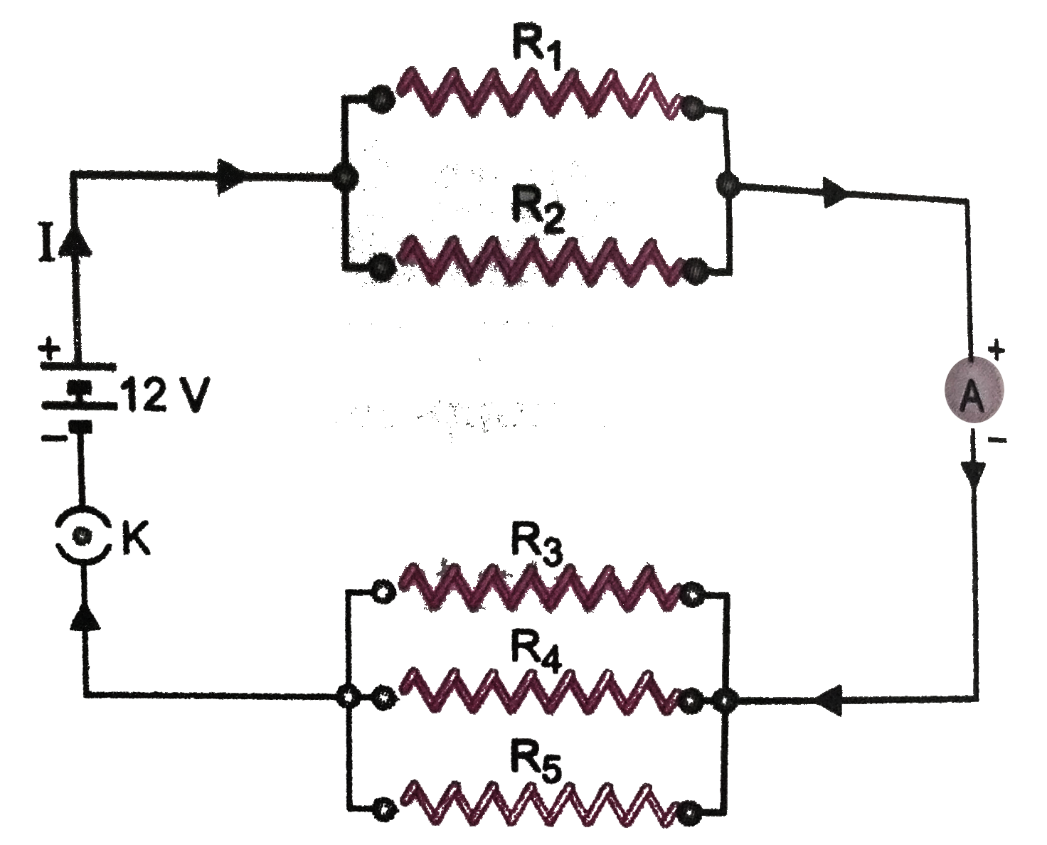
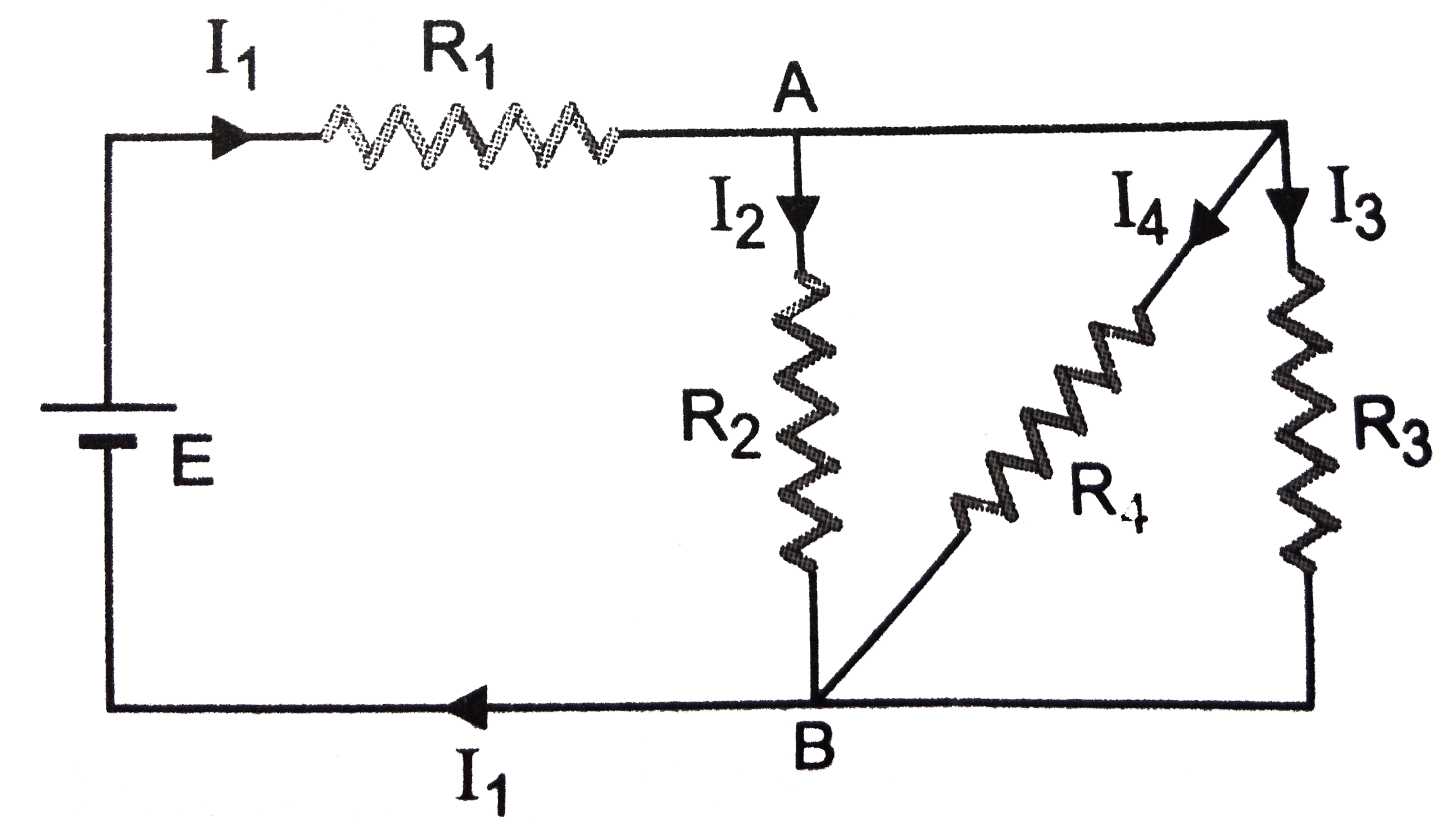
In R1=10Ω,R2=40ΩandR3=30Ω,R4=20Ω,R5=60Ω and a 12V battery is connected to the arrangement, calculate.
(a) the total resistance and
(b) the total current flowing in the circuit.
 .
.
(a) Since R1andR2 are in parallel, their resultant resistance (R'p) is given by
1R'p=1R3+1R4+1R5
=130+120+160=660=110
or R'p=10Ω
As RpandR'p are in series, total resistance in the circuit, Rs=Rp+R'p=8Ω+10Ω=18Ω
(b) Total current in the circuit, i.e., I=VRs=12V18Ω=0.67A.
Topper's Solved these Questions
Similar Questions
If in the figure R1=10Ω,R2=40Ω,R3=30Ω,R4=20Ω,R5=60Ω and a 12 V battery is connected to the arrangement, calculate (i) the total resistance in the circuit and (ii) the total current flowing in the circuit.
View SolutionIf in Fig. 12.12, R1=10Ω,R2=40Ω,R3=30Ω,R5=60Ω, and a 12 V battery is connected to the arrangemtn. Calculate (a) the total resistance in the circuit, and (b) the total current flowing in the circuit.
View Solution
Knowledge Check
In the R1=10Ω,R2=20Ω,R3=40ΩR4=80Ω and VA=5V,VB=10V,Vc=20V,VD=15V The current in the resistance R1 will be
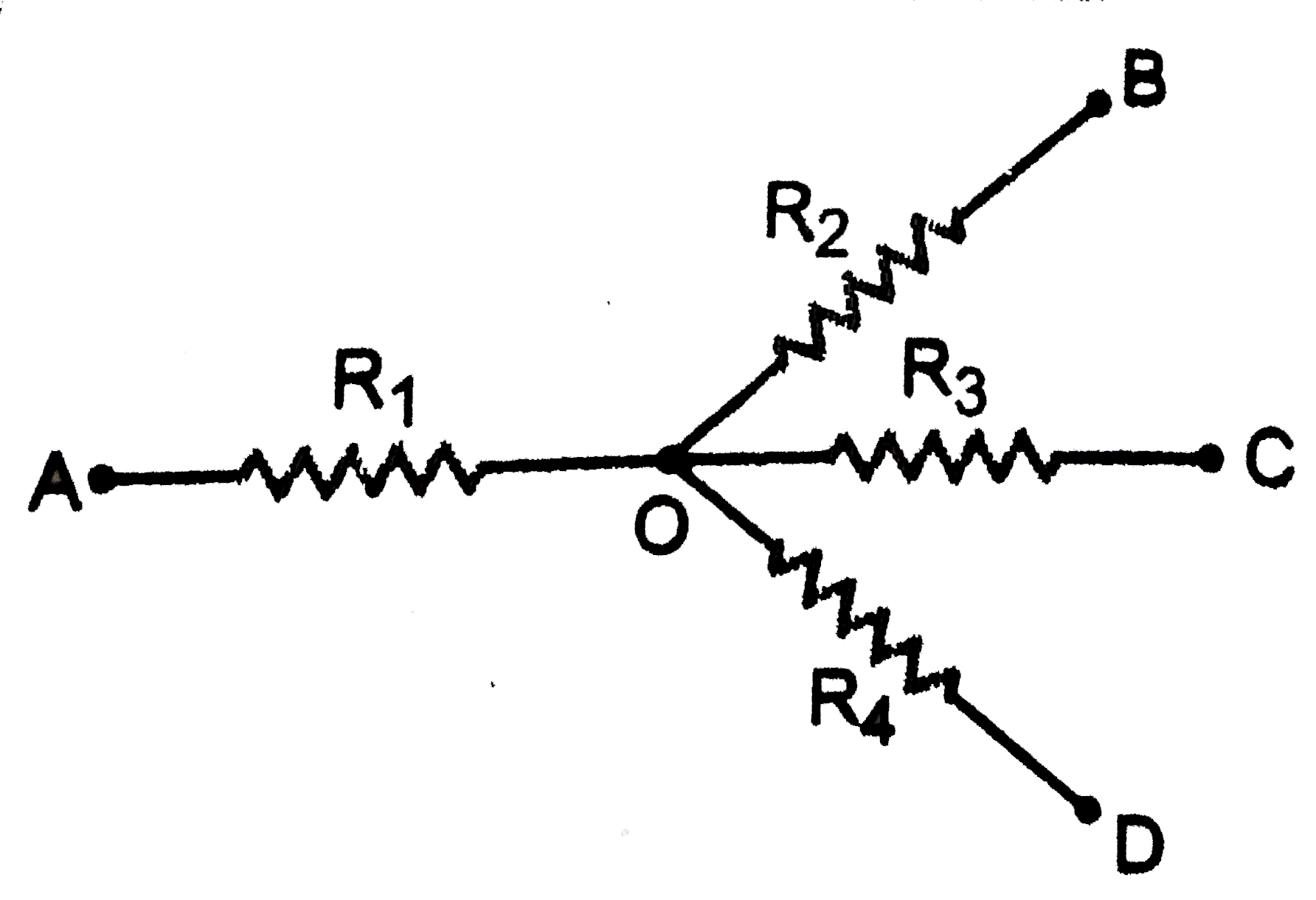 A0.4A toward OB0.4A away from OC0.8A toward OD0.8A toward O
In the circuit diagram given below five resistances of 10Ω,40Ω,30Ω,20Ω and 60Ω are connected as shown to a 12 V battery.
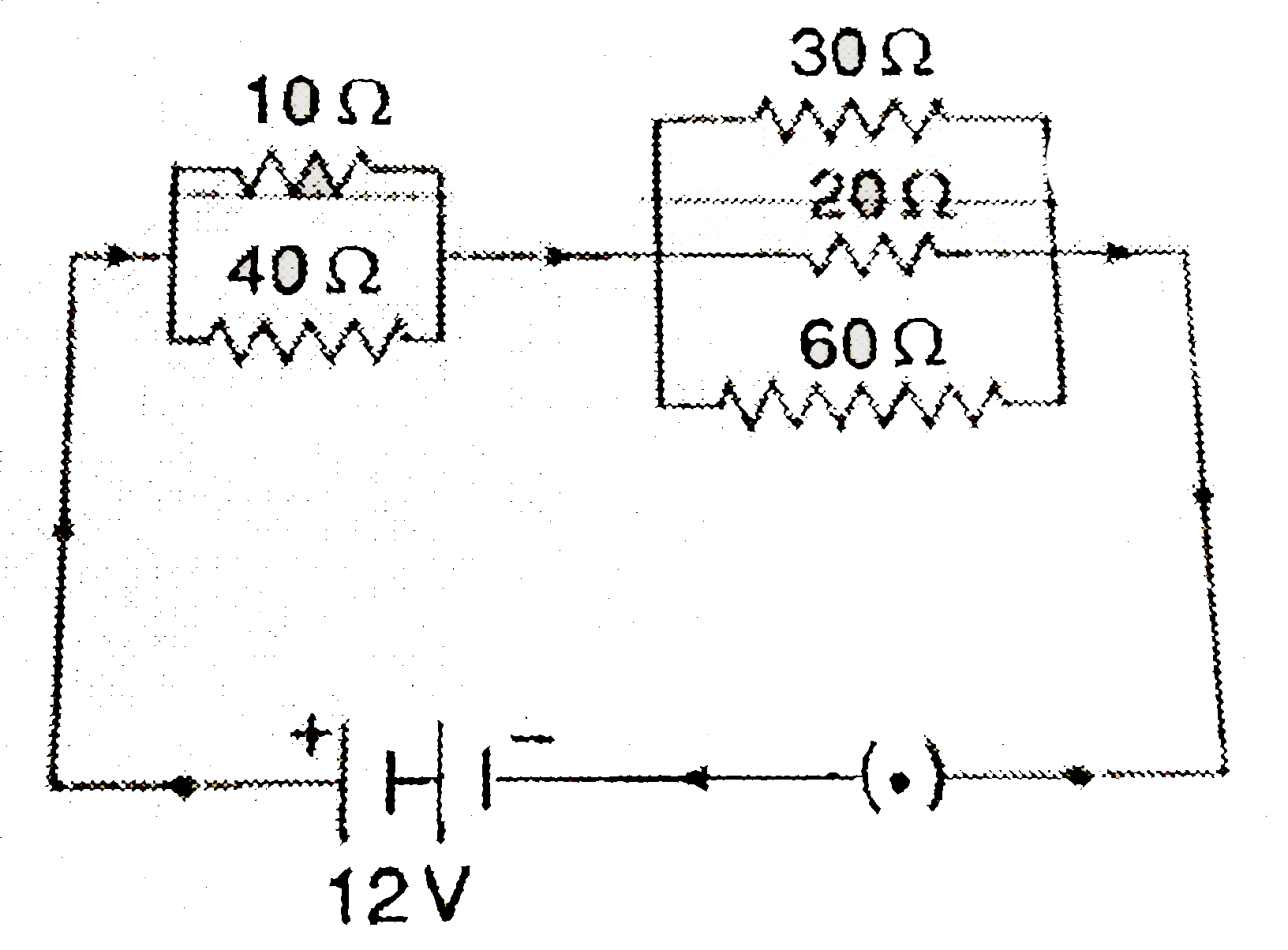
Calculate:
(a) total resistance in the circuit
(b) total current flowing in the circuit.
View SolutionIn the circuit diagram given below, three resistors R1,R2, and R3 of 5Ω,10Ω and 30Ω, respectively are connected as shown.
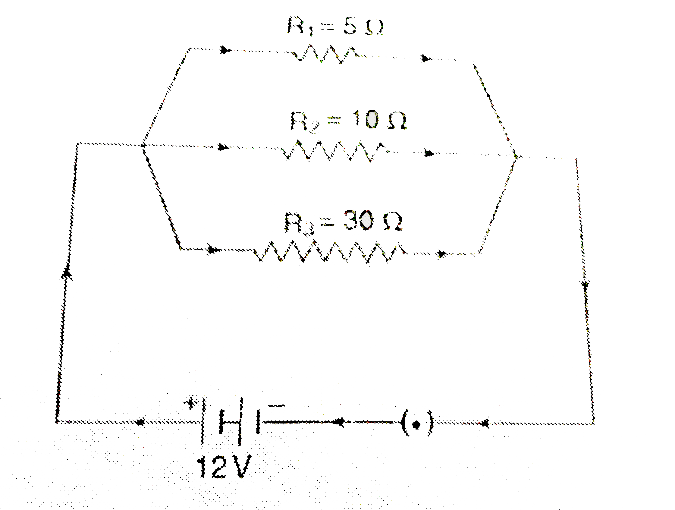
Calculate:
(a) current through each resistor.
(b) total current in the circuit.
(c) total resistance in the circuit.
View SolutionIn the circuit R1=4Ω,R2=R3=15ΩR4=30ΩandE=10V Calculate the equivalent resistance of the circuit and current in each resistor
View Solution(a) Resistors given as R1,R2andR3 are connected in series to a battery V. Draw the circuit diagram showing the arrangement. Derive an expression for the equivalent resistance of the combination.
(b) If R1=10Ω,R2=20ΩandR3=30Ω, calculate the effective resistance when they are connected in series to a battery of 6 V. Also find the current flowing in the circuit.
View SolutionIn Fig. 27-42, the resistances are R1=3.00Ω,R2=700Ω. and the battery is ideal. What value of R3 maximizes the dissipation rate in resistance 3?
View SolutionTwo resistances R1=(15±0.5)Ω and (20±0.7)Ω are connected in parallel. Calculate the total resistance of the combination and maximum percentage error.
View SolutionIn the circuit shown in Fig, the sources have emf'sξ1=1.5V,ξ2=2.0V,ξ3=2.5V , and the resistances are equal to R1=10Ω,R2=20Ω,R3=30Ω. The internal resistances of the sources are negligible. Find : ltbrtgt (a) the current flowing thorugh teh resistance R1 ,
(b) a potential differences φA−φB between the points A and B between the points A and B.

View Solution
