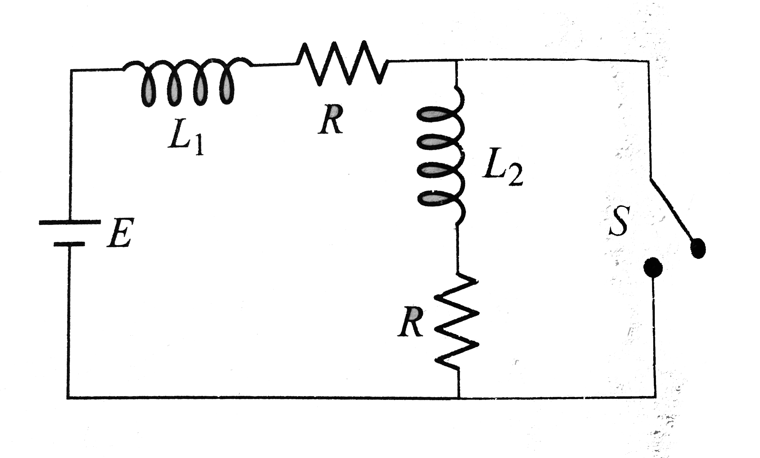
Switch S shown in Fig. is closed for t<0 and is opened at t=0. When currents through L1 and L2 are equal, their common value is
ER
E(L2+L2)RL1
EL1R(L1+L2)
ER(L1+L2)L2
The correct Answer is:C
Constancy of flux implies that ERL1=i(L1+L2)
i.e., i=EL1R(L1+L2)
Topper's Solved these Questions
- INDUCTANCEBOOK - CENGAGE PHYSICSCHAPTER - INDUCTANCEEXERCISE - Exercises (multiple Correct )
7 Videos
- INDUCTANCEBOOK - CENGAGE PHYSICSCHAPTER - INDUCTANCEEXERCISE - Exercises (assertion-reasoning)
2 Videos
- INDUCTANCEBOOK - CENGAGE PHYSICSCHAPTER - INDUCTANCEEXERCISE - Exercises (subjective)
7 Videos
- HEATING EFFECT OF CURRENTBOOK - CENGAGE PHYSICSCHAPTER - HEATING EFFECT OF CURRENTEXERCISE - Thermal Power in Resistance Connected in Circuit
28 Videos
- KINETIC THEORYBOOK - CENGAGE PHYSICSCHAPTER - KINETIC THEORYEXERCISE - Question Bank
31 Videos
Similar Questions
Knowledge Check
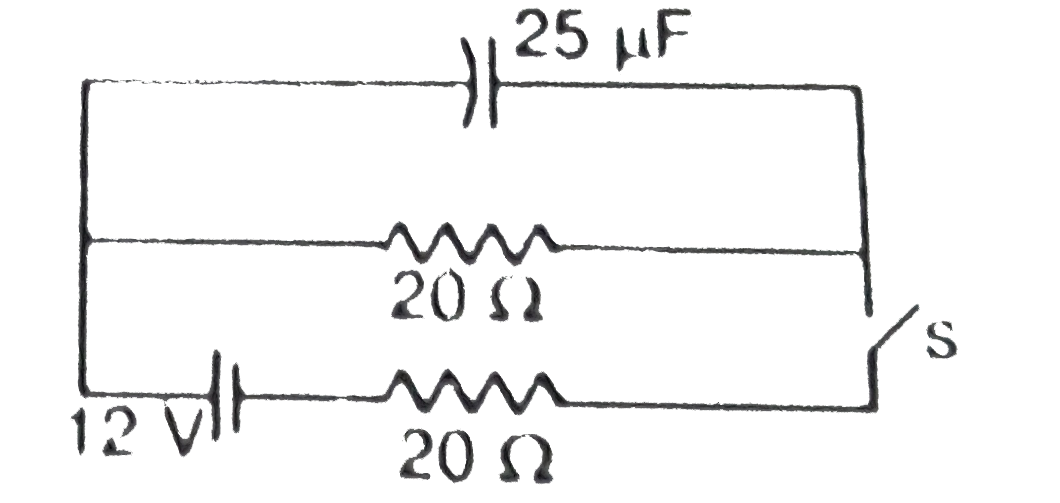
The switch S shown in figure is kept closed for a long time and then opened at t = 0, then the current in the middle 20Ω resistor at t=0.25 ms is :
 A0.629AB0.489AC0.189AD23 mA
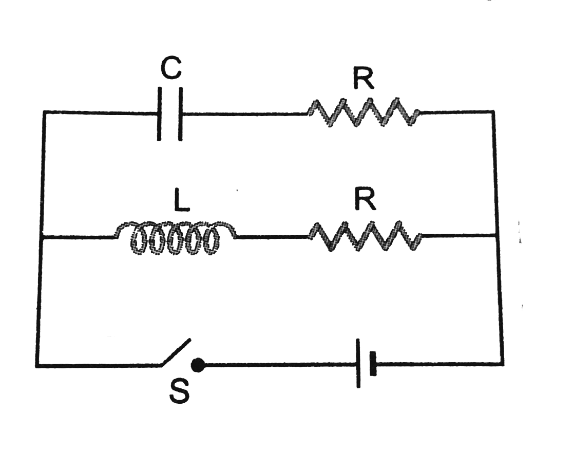
In the circuit shown if Fig. the switch S is closed at time t = 0. The current through the capacitor and inductor will be equal at time t equal (given R=√L/C
 ARCBRCloge2C1RlogeDLR
In Fig. switch S is closed for a long time. At t=0, if it is opened, then
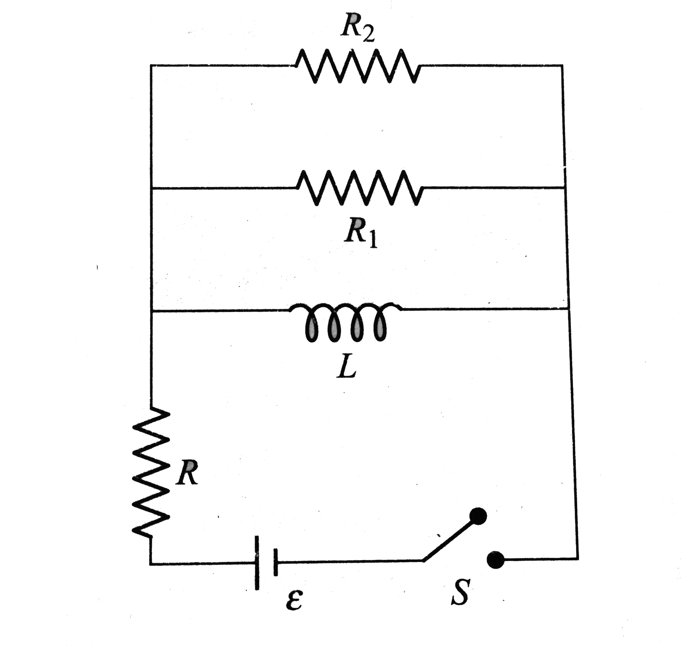 Atotal heat produced in resistor R after opening the switch is 12LεR2Btotal heat produced in resistor R1 after opening the switch is 12Lε2R2(R1R1+R2)Cheat produced in resistor R1 after opening the switch is 12R2Lε2(R1+R2)R2Dno heat will be produced in R1
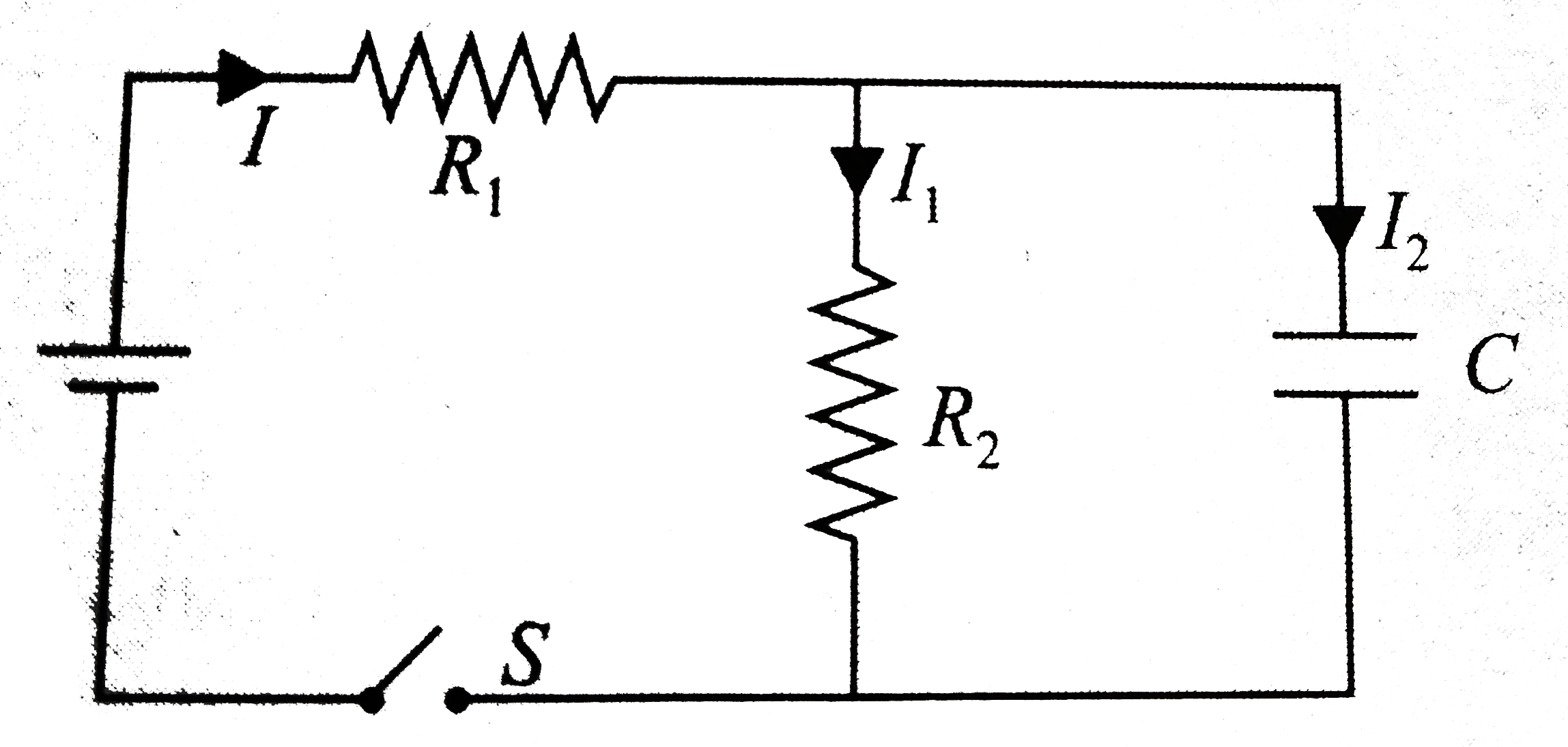
Consider the circuit shown in fig. If the switch is closed at t =0, then calculate the values of I,I1 and I2 at a. t =0 , b. =∞
View SolutionSwitch S of the circuit shows in Fig. is closed at t=0. If e denotes the induced emf in L and i the current flowing through the circuit at time t, then which of the following graphs correctly represents the variation of e with i?
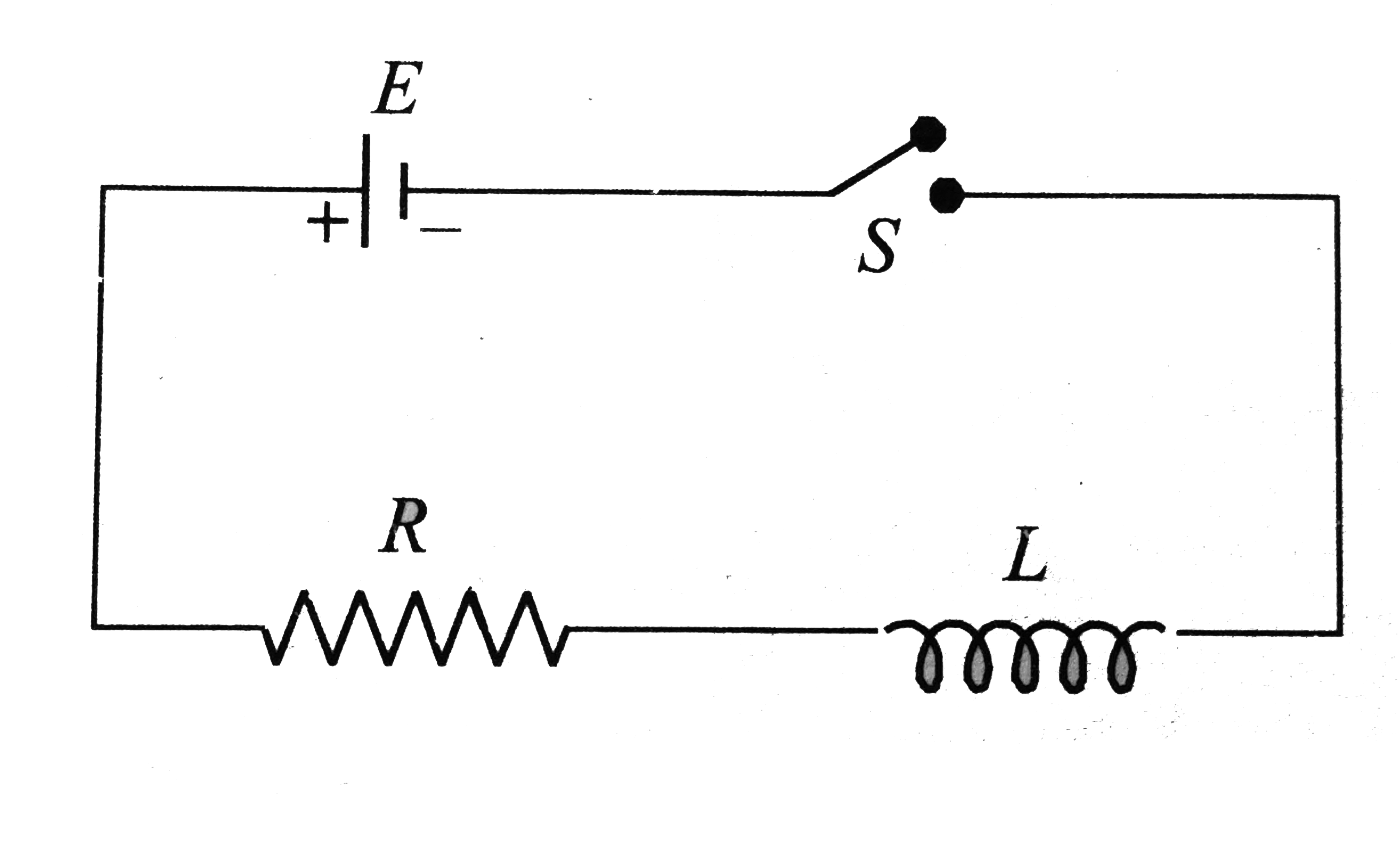
View SolutionThe switch shown in figure is closed at t=0 find the charge throuh battery till time t=LR
_2019_CBT8_E01_016_Q01.png)
View SolutionIn the circuit shows in Fig the switch is closed at t=0.

View SolutionSwitch S of the circuit shows in Fig is closed at t=0. If e denotes the induced emf in L and I is the current flowing through the circuit the circuit at time t, which of the following graphs is//are correct?

View Solution

_PHY_E06_157_Q01.png)