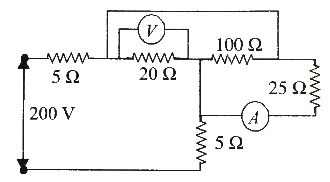
In Fig.6.61 the voltmetre and ammeter shows are ideal. Then voltmeter and ammeter readings, respectively, are
A
125V,3A
B
100V,4A
C
120V,4A
D
120V,3A
Video Solution
Text Solution
The correct Answer is:B
Resistors 20Ω, 100Ω, and
25Ω will be in parallel.
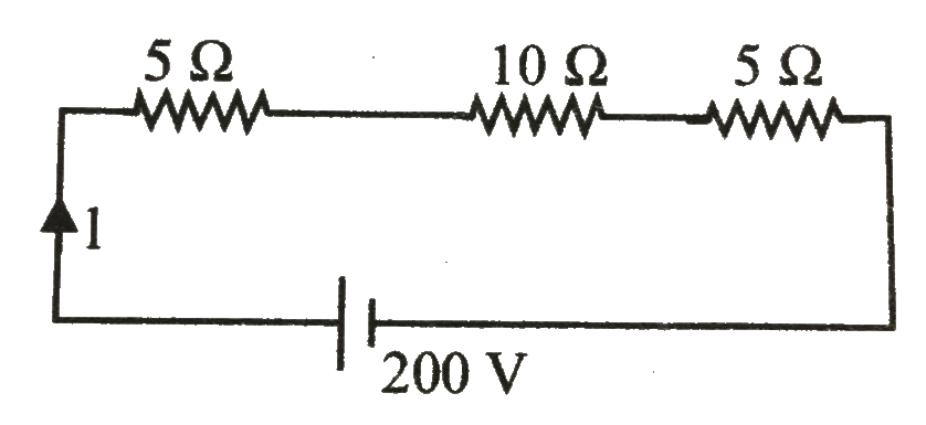
Their equivalent is 10Ω.
I=2005+10+5=10A
Potential difference across 10Ω is 10I=10×10=100V
This will be the voltmeter reading. Also, this will be the potential difference across each of 20Ω, 100Ω, and 25Pmega resistors.
Ammetre reading = current through 25Ω=10025=4A
|
Topper's Solved these Questions
- ELECTRICAL MEASURING INSTRUMENTSBook:CENGAGE PHYSICSChapter:ELECTRICAL MEASURING INSTRUMENTSExercise:Multiple Correct
Explore 7 Videos
- ELECTRICAL MEASURING INSTRUMENTSBook:CENGAGE PHYSICSChapter:ELECTRICAL MEASURING INSTRUMENTSExercise:Assertion-Reasoning
Explore 7 Videos
- ELECTRICAL MEASURING INSTRUMENTSBook:CENGAGE PHYSICSChapter:ELECTRICAL MEASURING INSTRUMENTSExercise:Subjective
Explore 18 Videos
- ELECTRIC POTENTIALBook:CENGAGE PHYSICSChapter:ELECTRIC POTENTIALExercise:DPP 3.5
Explore 14 Videos
- ELECTROMAGENTIC INDUCTIONBook:CENGAGE PHYSICSChapter:ELECTROMAGENTIC INDUCTIONExercise:QUESTION BANK
Explore 40 Videos
Similar Questions
Knowledge Check
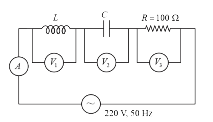
In the series L-C-R circuit , the voltmeter and ammeter readings are respectively
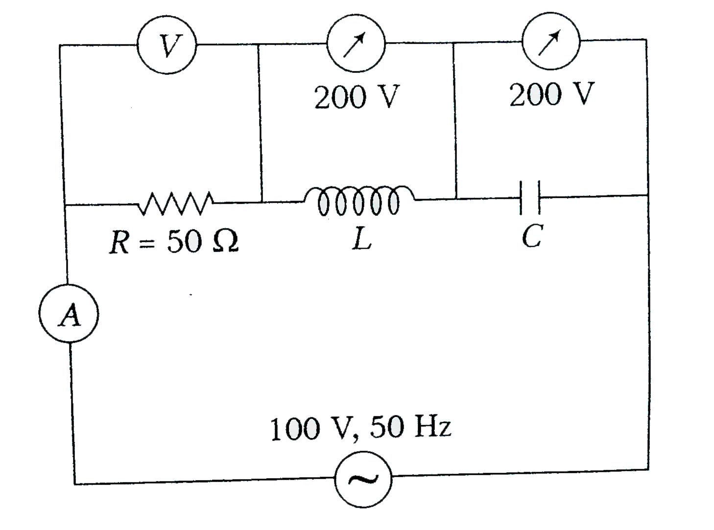 AV = 200 V , I = 4 ABV = 150 , I = 2 ACV = 100 , I = 5 ADV = 100 V, I = 2 A
In the series L-C-R circuit , the voltmeter and ammeter readings are
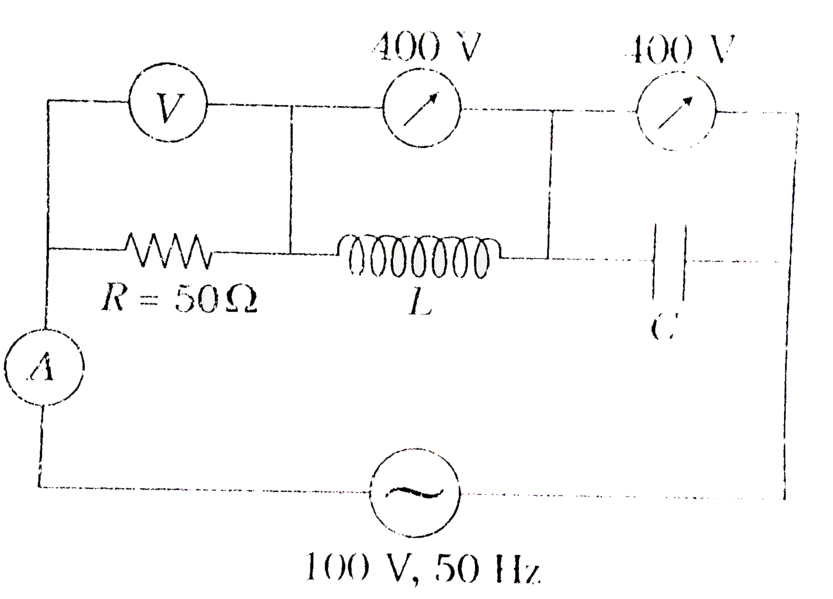 AV = 100 V, I = 2 ABV = 100 V , I = 5 ACV = 1000 V, I = 2 ADV = 300 V , I = 1 A
In the circuit in figure, V is high resistance voltmeter and A is a low resistance ammeter. Switch S is open. What is the effect on the voltmeter and ammeter reading when switch S is now closed? Voltmeter reading and Ammeter reading respectively
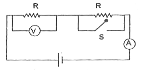 AReading of voltmeter and Ammeter increasesBVoltmeter reading increase and Ammeter reading decreaseCVoltmeter reading increase while the ammeter reading remains sameDVoltmeter reading decreases and ammeter reading decreases
In the series LCR circuit as shown in the figure, the voltmeter V and ammeter A reading are
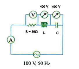
View SolutionWhat is the resistance of ideal ammeter and ideal voltmeter?
View Solution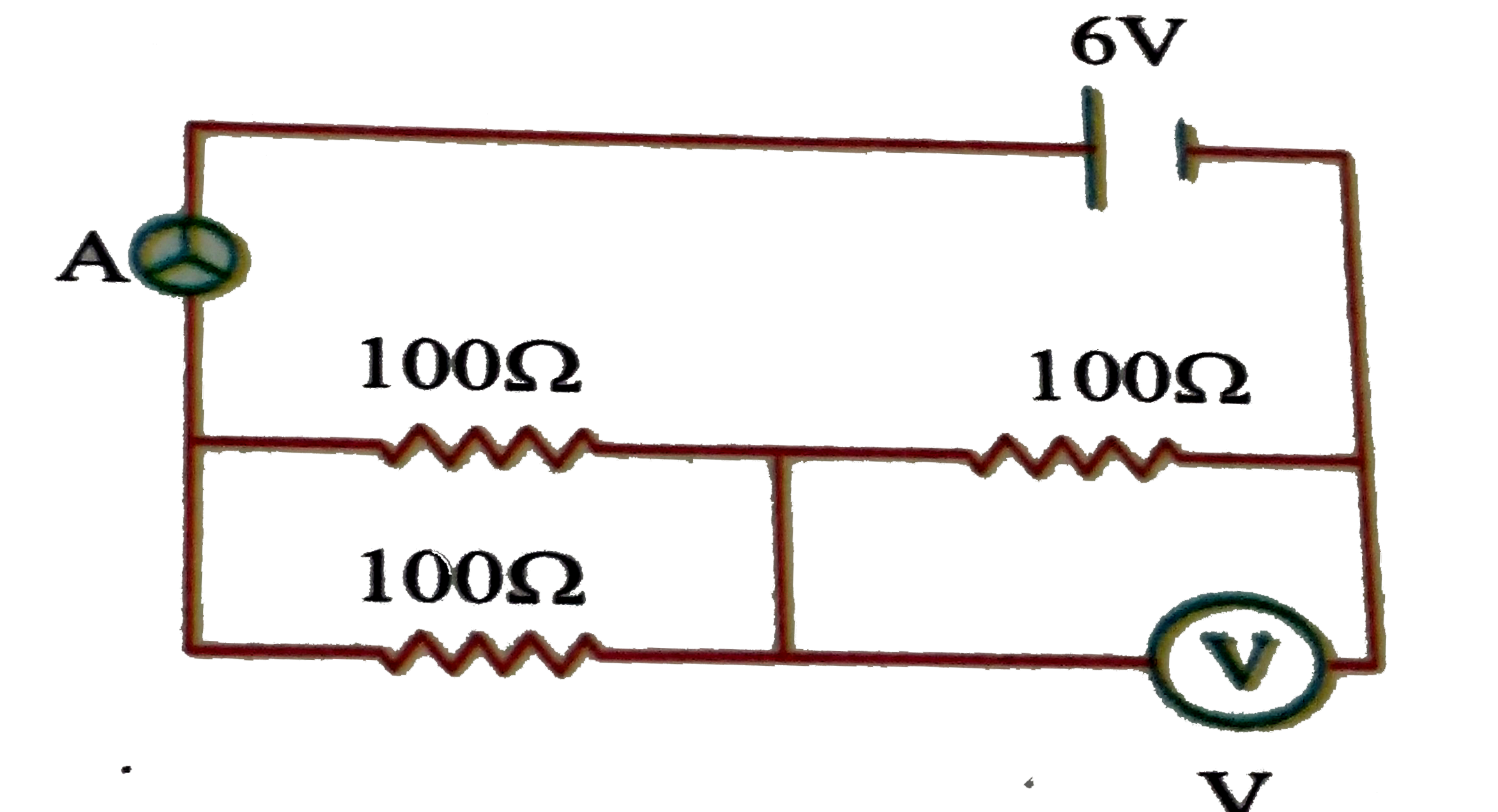
In the circuit shown, the reading of the voltmeter and the ammeter are
View SolutionIn the circuit shown in figure neglecting source resistance the voltmeter and ammeter reading will respectively, will be
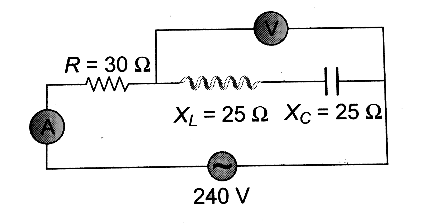
View SolutionIn the given circuit the reading of voltmeters V1andV2 are 300 volt each . The reading of the voltmeter V3 and ammeter A are respectively
View Solution

