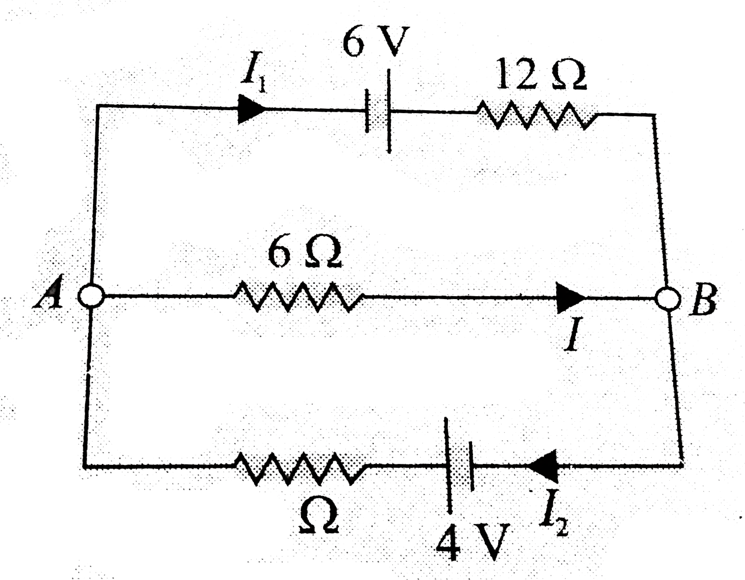
In the circuit shown,
i. V_A - V_B = ……..
(ii) I_1 = …….
(iii) I_2 ……..
iv. I = ……..
Video Solution
Text Solution
The given cirucit may be replaced by an equivalent battery of emf and resistanace r as shown in fig 5.102
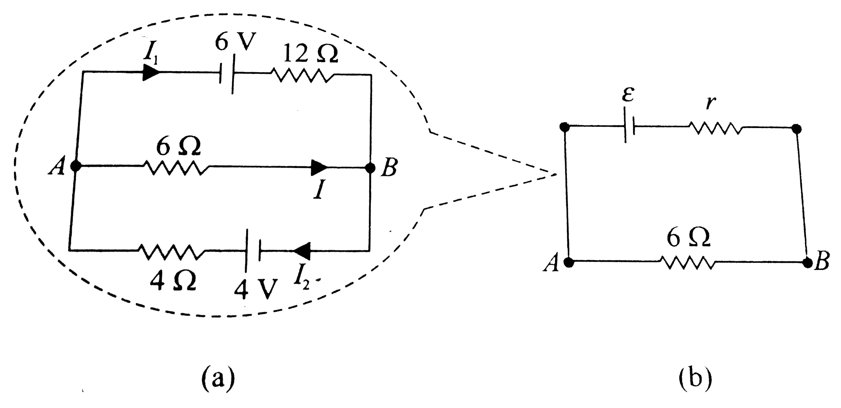
and

Thus, current through the external resistor is (From A to B)
For potential difference
or
For upper branch:
or
For lower branch:
or
Method 2. Instead of making equivalent battery of two
bracnhes, we can make equivalent battery fo all three branches.
in the middle bracnh, we can assume a battery of zero emf
connected with resistance The given ciruit may be
replaced by an equivalent battery of emf and resistance r as
shwon in fig 5.103
and
This battery is an open cirucit battery, hence potential
differecne across each branch will be 1V. Now we will get the
saem result as we have in previous method.
|
Topper's Solved these Questions
- ELECTRIC CURRENT AND CIRCUITBook:CENGAGE PHYSICSChapter:ELECTRIC CURRENT AND CIRCUITExercise:Solved Examples
Explore 12 Videos
- ELECTRIC CURRENT AND CIRCUITBook:CENGAGE PHYSICSChapter:ELECTRIC CURRENT AND CIRCUITExercise:Exercise 5.1
Explore 28 Videos
- ELECTRIC CURRENT & CIRCUITSBook:CENGAGE PHYSICSChapter:ELECTRIC CURRENT & CIRCUITSExercise:Kirchhoff s law and simple circuits
Explore 15 Videos
- ELECTRIC FLUX AND GAUSS LAWBook:CENGAGE PHYSICSChapter:ELECTRIC FLUX AND GAUSS LAWExercise:MCQ s
Explore 38 Videos
Similar Questions
Knowledge Check
In the circuit shown, the currents i1 and i2 are
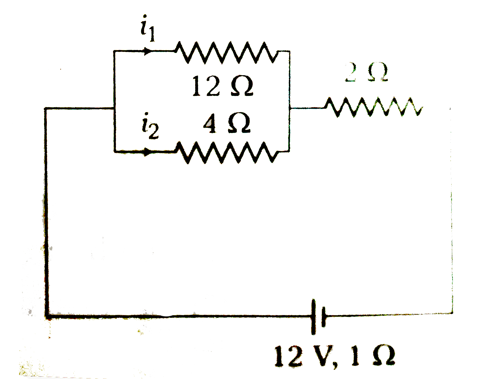 Ai1=1.5A,i2=0.5ABi1=0.5A,i2=1.5ACi1=1A.i2=3ADi1=3A,i2=1A
In the circuit, the battery is ideal. A voltmeter of inifinite resistance is connected in turn across R1 and R2, giving reading of V1 and V2 respectively.
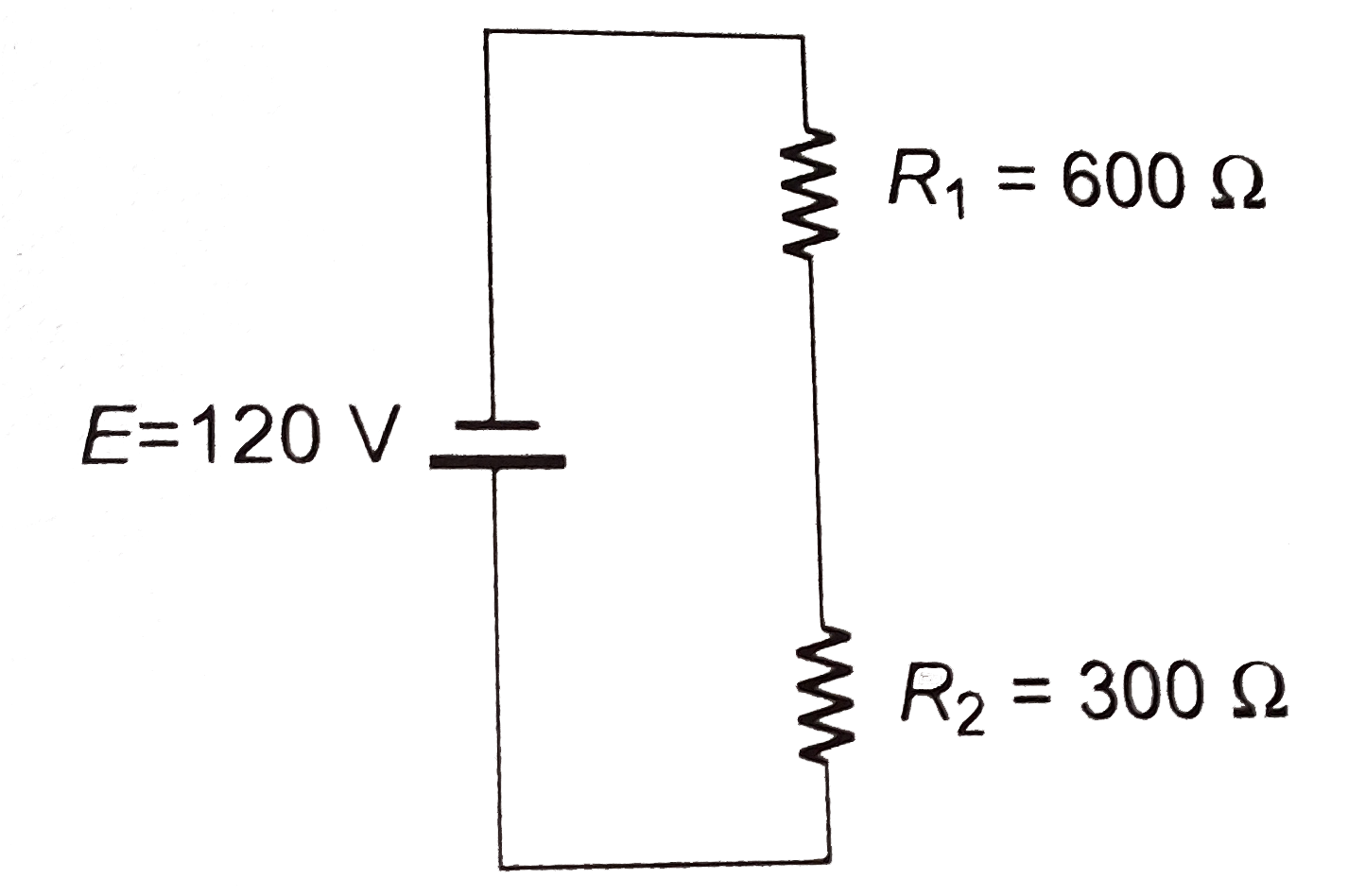 .
.
(i) V1=80V
(ii) V1=60V
(iii) V2=30V
(iv) V2=40V.A(i),(ii)B(ii),(iii)C(iii),(iv)D(i),(iv)In the circuit shown, the value of currents I1,I2andI3 are
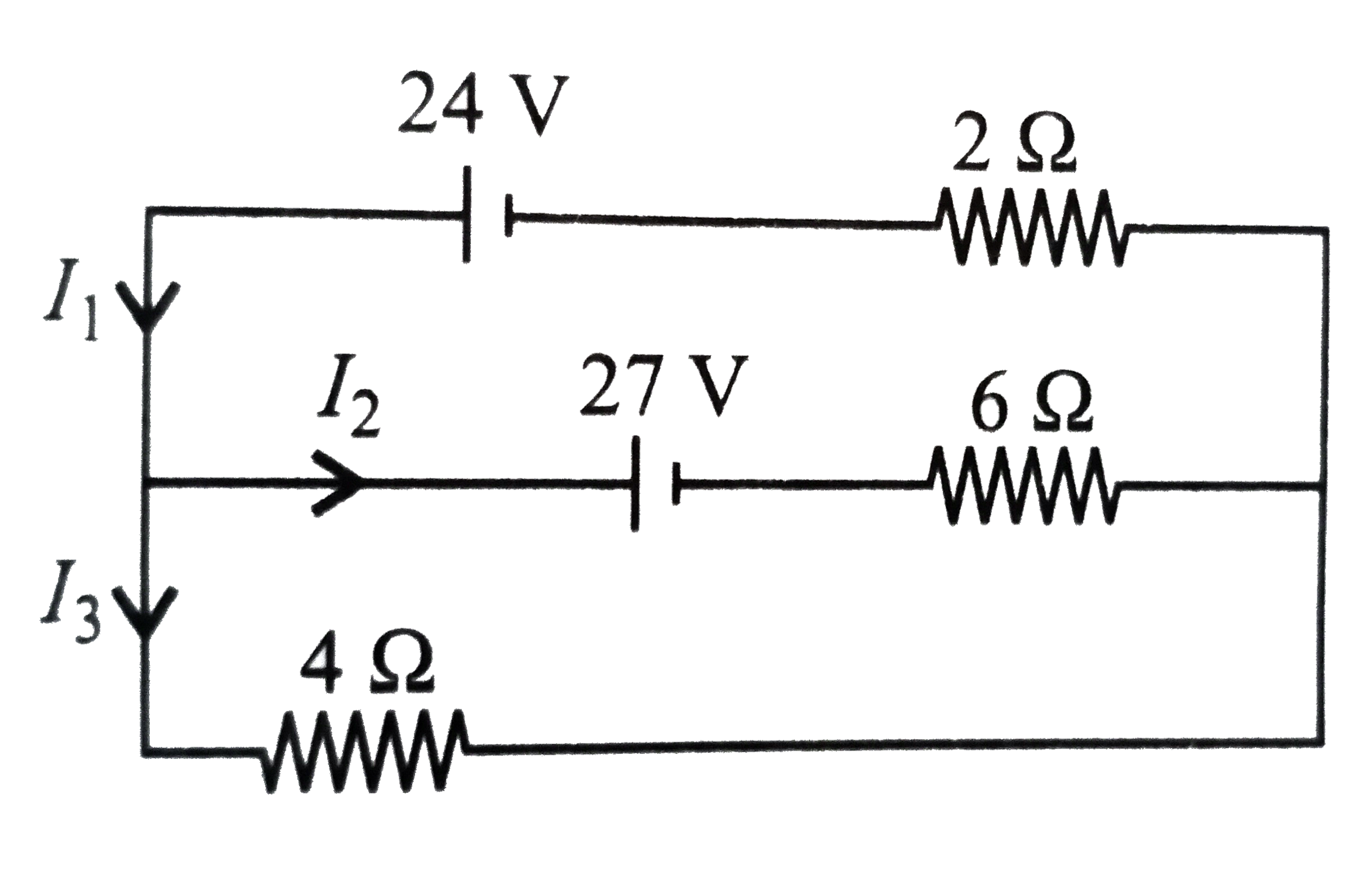 A3A,−3A2A,92AB92A,−32AC5A,4A,−3AD7A,54A,92A
In the circuit, shown in fig vs=0.2V,v0=−10V. Find vi and gain Av=v0/vi and A′v=v0vs?
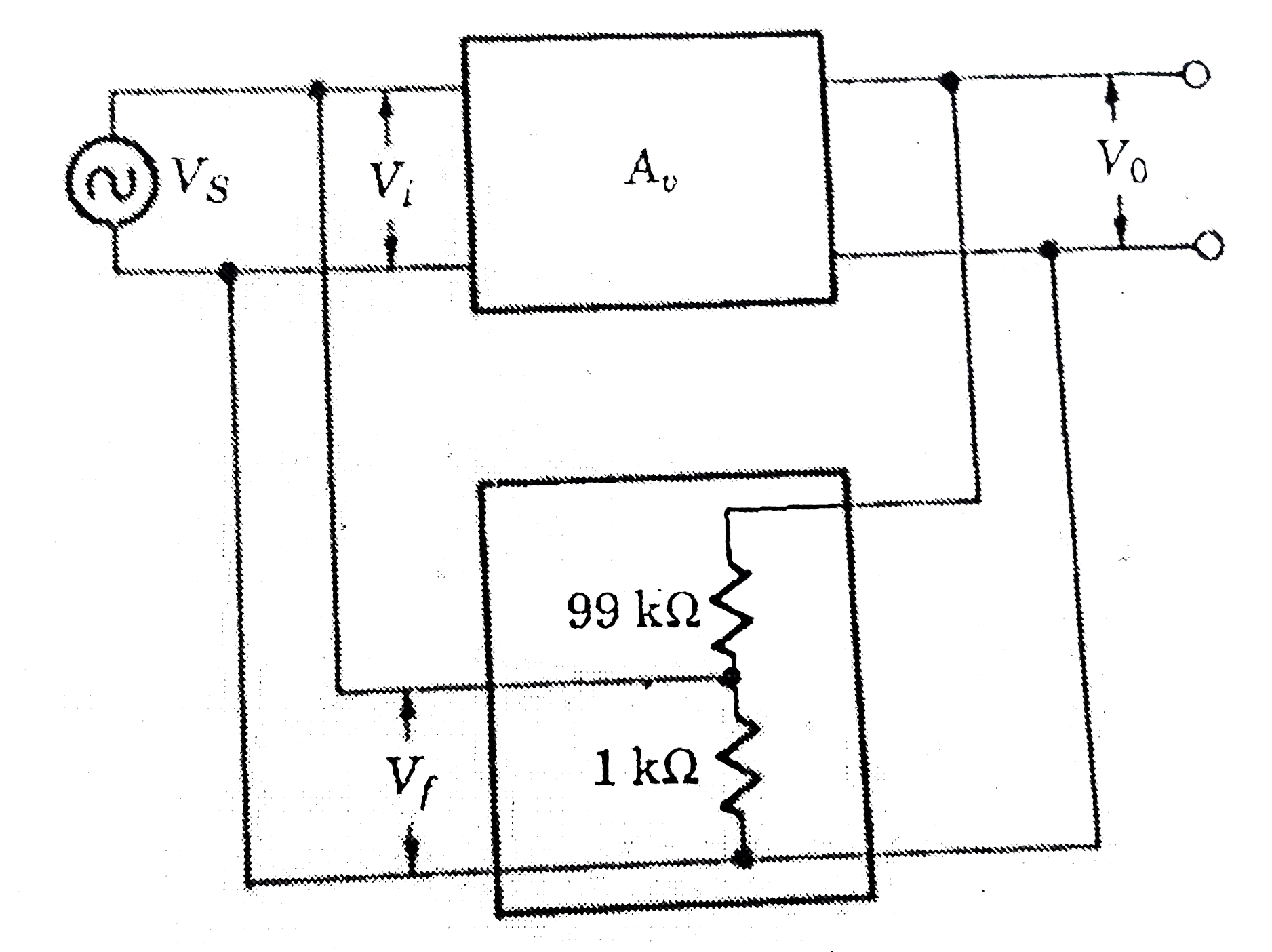
View Solution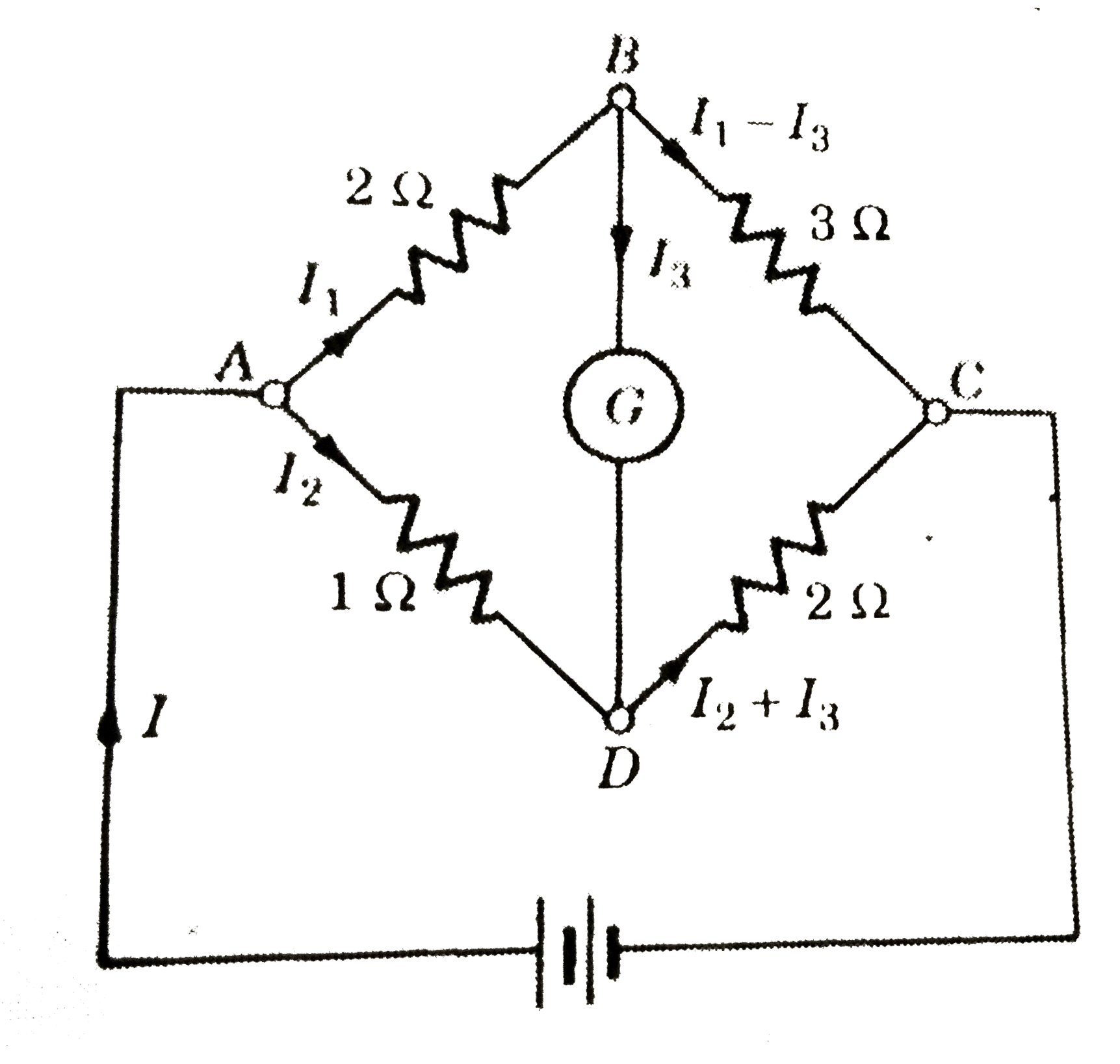
In the circuit shown in figure. Find the currents I,I1,I2andI3 given that emf of th battery=2V, internal resistance of the battery =2Ω and resistance of the galvanomter =4Ω.
View SolutionGive the magnitude and polarity of the following voltages in the circuit of figure:
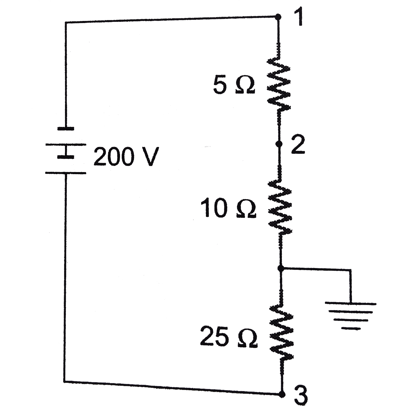
i. V1 ii. V2 iii. V3 iv. V3−2
v. V1−2
V1−3
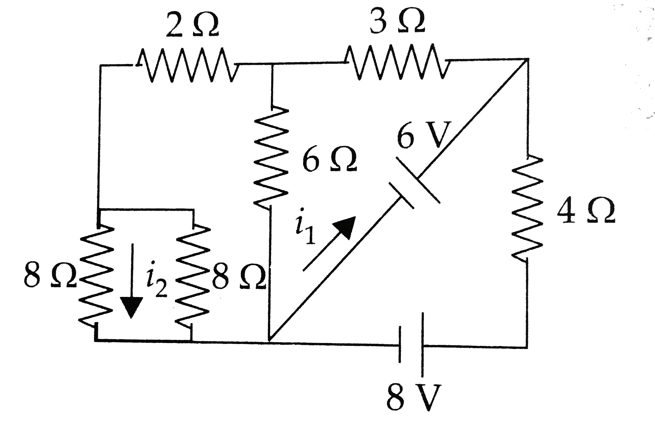
View SolutionIn the circuit as shown in figure, the ratio of current i1/i2 is
View Solution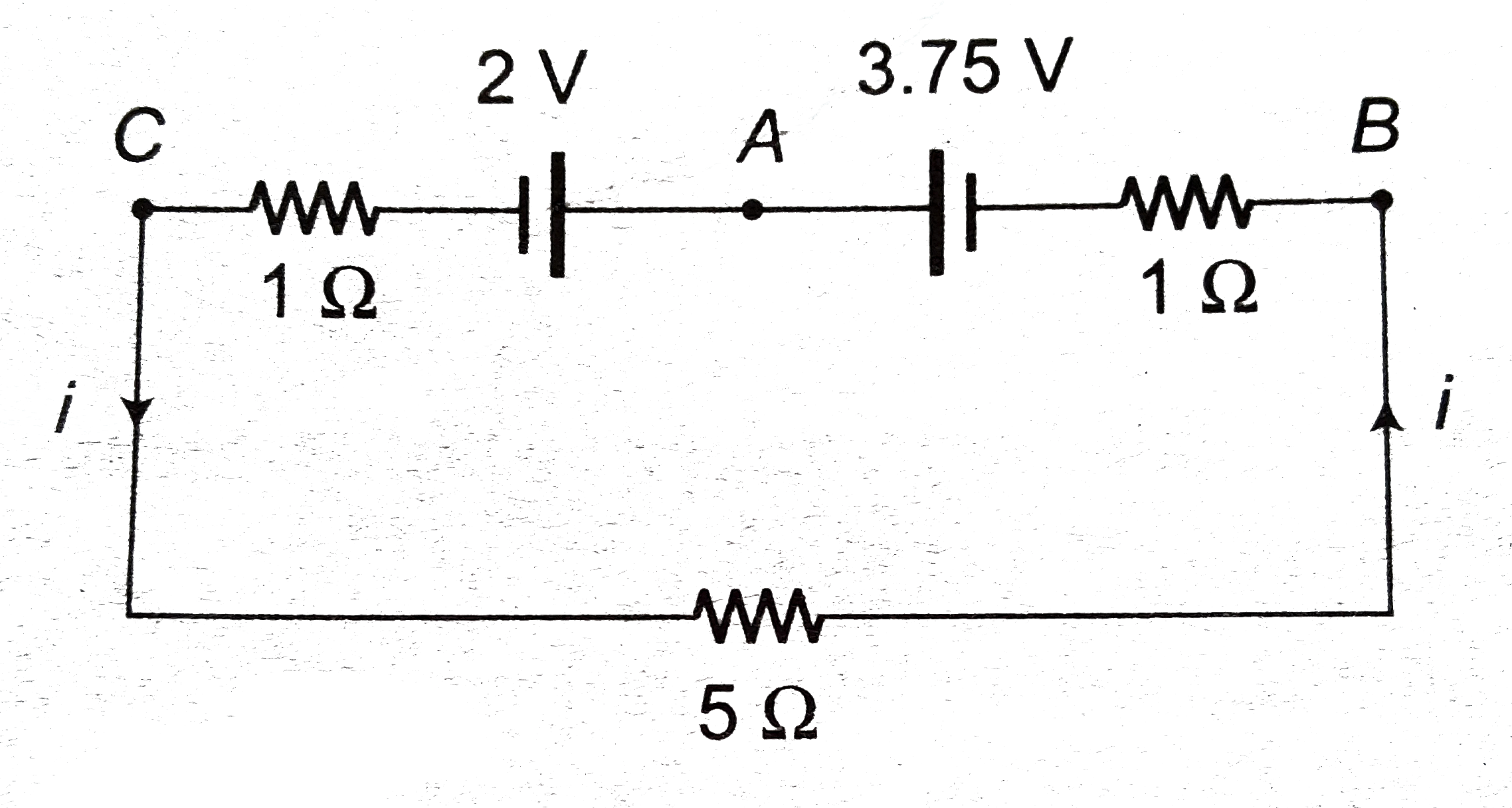
(i) i=0.25A
(ii) VA−VB=3.5V
(iii) VA−VC=2.25V
Equivalent resistance =7Ω.
View Solution


